Solar Panel Monitoring System Built with XIAO ESP32C3
This project provides an affordable and accessible solution for monitoring solar photovoltaic (PV) systems, which can help maximize the benefits of renewable energy and reduce their carbon footprint. By providing real-time data on the performance of solar panels, the system empowers us to take proactive steps to optimize solar PV systems and reduce energy costs.
The project provides step-by-step instructions for building the monitoring system, including how to set up the XIAO ESP32C3, connect the current sensor, and configure the system to send data to the web server. The project also includes information on how to access and analyze the data using a web interface.
Seeed Hardware: Seeed Studio XIAO ESP32C3
Software: Blynk
Industry: Energy
Background
Monitoring and controlling the performance of solar PV systems is essential for maximizing energy production, reducing costs, ensuring system reliability, and ensuring safety. By using a monitoring system, users can proactively identify and address any issues that may arise, leading to a more efficient and effective solar PV system.
The Challange
Building a solar panel monitoring system requires careful consideration of data collection, compatibility, power consumption, weather conditions, maintenance, and data analysis. By addressing these challenges, it is possible to build an effective and reliable monitoring system that provides valuable insights into the performance of solar panels.
The Solution
- Hardware Preparation
The ACS758 is a highly accurate and robust linear current sensor that uses Hall Effect to provide an analog voltage output proportional to the sensed current. It is capable of measuring both AC and DC currents, making it ideal for monitoring power flow in solar PV systems.
To convert the analog voltage signal from the ACS758 into a digital format that can be processed by the Xiao ESP32C3, a precision 16-bit Analog to Digital Converter (ADC) called ADS1115 is used.
As the voltage output from the solar panel can be high, a voltage divider circuit is used to step down the voltage to a safe level that can be measured by the ADC. The voltage divider circuit utilizes two resistors to divide the input voltage into a smaller, proportional voltage.
Temperature changes can affect the efficiency of solar panels, so a digital temperature sensor called DS18B20 is used to provide high-precision temperature readings over a wide range.
The Xiao ESP32C3 is a compact and feature-rich microcontroller that processes the data received from the ADC and temperature sensor and relays the information to the OLED display. It also provides IoT capabilities such as remote monitoring through its Wi-Fi and Bluetooth functionalities.
To step down the voltage from the solar panel to a safe 5V level to power the Xiao ESP32, a high-performance and adjustable step-down DC-DC module called XL7015 is used.
Finally, an OLED display is used to present the processed data in a clear and readable format, offering high contrast, low power consumption, and wide viewing angles.
In addition, a battery connector is integrated into the system to store excess energy during the day and provide power to the board during night-time or periods of low sunlight, ensuring the continued operation of the monitoring system.
2. Working Principle
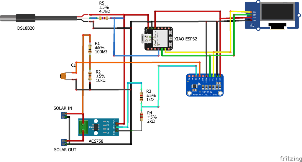
3. Schematic Diagram

4. Measuring Voltage
The solar panel voltage is sensed using a voltage divider network consisting of two resistors R1=100k and R2=10k. The output is connected to ADC1115 pin A0 and smoothed using a ceramic capacitor C1.
The equation for the voltage divider circuit is Vout = R2/(R1+R2) x Vin. The ads.readADC_SingleEnded(0) function reads the raw analog data which is then converted to voltage using Vin = Raw Voltage *(R1+R2)/R2.
To use solar panels with higher voltage, select appropriate resistors R1 and R2. Use an online calculator to select the voltage divider resistance values.
5. Measuring Current
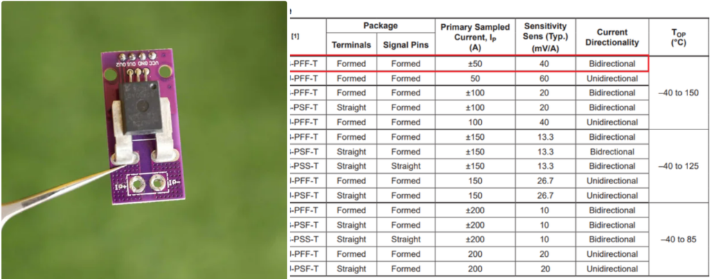
To measure current, Hall Effect current sensor called ACS758-50B is used, which converts the current value into a voltage value using sensitivity. The sensitivity value can be found in the datasheet, which is 40mV/A. The output from the current sensor is connected to a voltage divider network consisting of resistors R3 and R4. To calculate the current, use the formula: Current (A) = (ADCVoltage – Offset Voltage) / sensitivity. ADCVoltage is obtained by multiplying the analogRead(Pin) value with the ADC gain and the voltage divider factor (R3+R4)/R3. The offset voltage is Vcc/2 (2.5V).
6. Measuring Current
For measuring ambient temperature, I used an external DS18B20 probe that communicates using a one-wire protocol. It requires a pull-up resistor connected to its signal line, which I achieved using a 4.7K resistor (R5) connected to a 3-pin screw terminal on the PCB. To interface with the DS18B20 temperature sensor, install the One Wire library and the Dallas Temperature library. Refer to this article for more details. Connect the red wire to Vcc, the yellow wire to DATA, and the black wire to GND, as labeled on the PCB.
7. Interfacing OLED Display
To display solar panel parameters locally, a 0.96″ OLED display is used with a 128 x 64 resolution that communicates over I2C using SDA (GPIO21) and SCL (GPIO22) pins on the ESP32. To connect, use the ESP32’s 3.3V pin for VCC and GND for GND, and connect the SDA and SCL pins to the corresponding pins on the OLED display. Note that you can also use an I2C LCD display by modifying the code appropriately.
8. Seeed Studio Fusion Agile Manufacturing from 0.1 to ∞
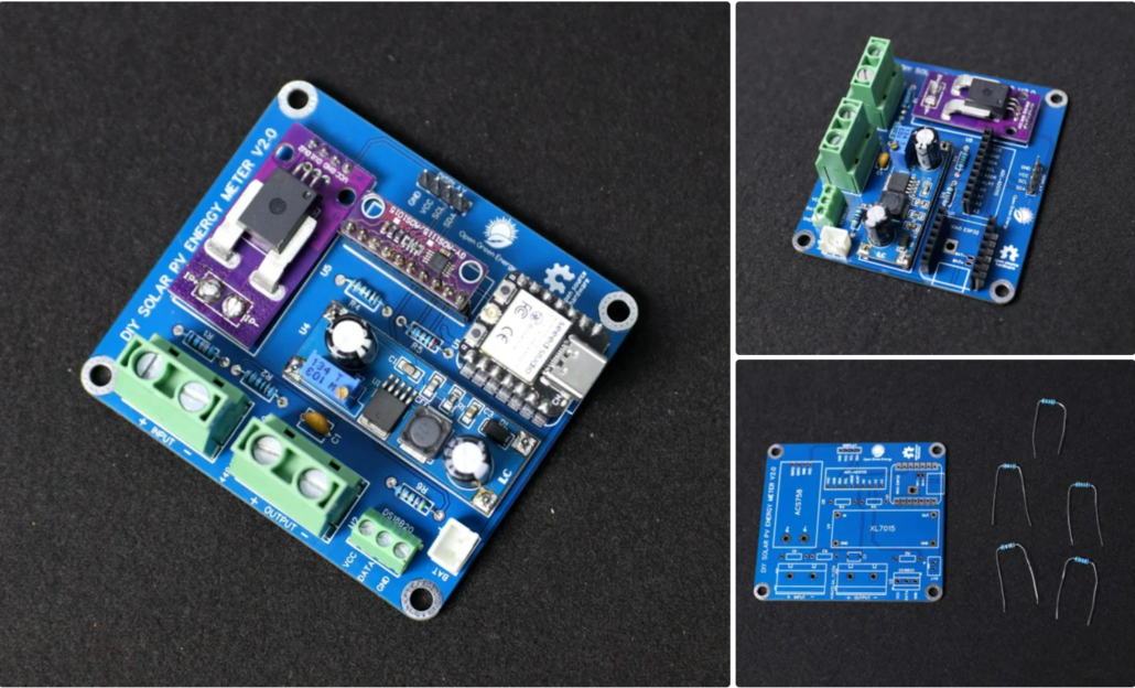
To solder the components:
- Insert the component legs through the PCB holes and flip it over.
- Heat the junction of the pad and component leg with a soldering iron.
- Apply solder to the joint so that it flows around the lead and covers the pad.
Get unrivaled speed and efficiency when you innovate with vast resources in Shenzhen China. Learn more at Seeed Fusion. Send us your project plan today for a quotation.
- From prototype to mass production, accelerate time-to-market with Seeed Fusion
- Original Design Manufacturing (ODM) and Customization Solutions.
9. 3D Printed Enclosure
10. Software and Libraries
To use the XIAO ESP32 board with the Arduino library, you’ll have to use the Arduino IDE with ESP32 board support.
If you haven’t already done that yet, you can easily install ESP32 Board support to your Arduino IDE by following this tutorial by Sparkfun.
Install the Libraries:
Before uploading the code install the following libraries :
2. Blynk
4. One Wire
11. Interfacing With Blynk 2.0
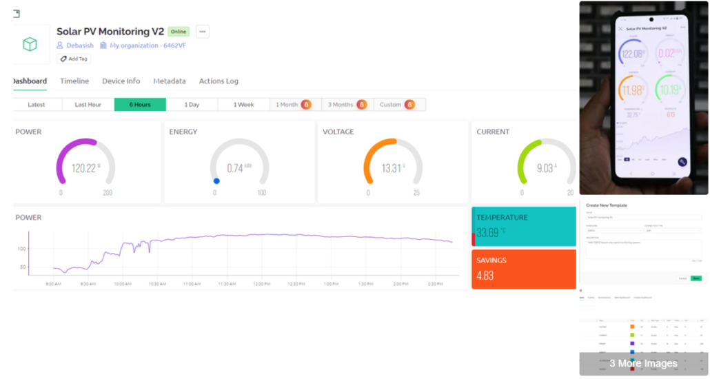
Blynk 2.0 lets you create custom dashboards for monitoring sensor data. To set up web and mobile dashboards with four gauges, two labels, and one graph:
- Sign up for a Blynk 2.0 account and create a new project for your device.
- Add data streams for voltage, current, power, energy, temperature, and savings, and assign virtual pins from V0 to V5.
- Add a new device and save the authentication token.
- Create web and mobile dashboards by dragging and dropping widgets and setting their parameters.
- Sync the project with your device using the authentication token in your Arduino code.
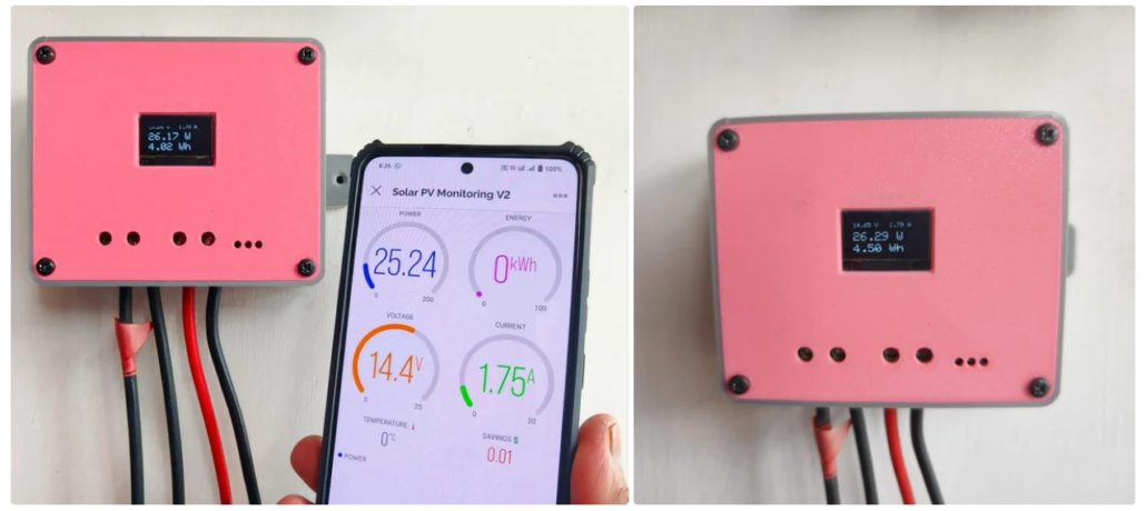
12. Field Testing
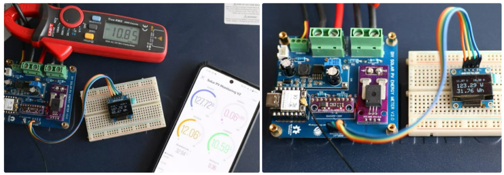
To field test the device:
- Connect the load’s negative terminal to the output negative terminal, and positive terminal to the output positive terminal. Connect the output terminal to the inverter.
- Connect the solar panel’s negative terminal to the input negative terminal, and positive terminal to the input positive terminal.
Use wire sizes from 26 – 10 AWG for the input and output screw terminals.
Note: Ensure correct polarity to avoid damage. The circuit does not have reverse polarity protection.
Once connected, check the solar panel parameters on the OLED display and on the Blynk app on your smartphone.
The Conclusion
This project is a DIY Solar PV Monitoring System V2.0 that measures various parameters such as voltage, current, power, energy, and temperature of a solar panel system. The system consists of an XIAO ESP32C3, a voltage divider network, a Hall Effect current sensor, an external DS18B20 probe, a 0.96″ OLED display, and Blynk 2.0 IoT platform for monitoring and displaying data. The microcontroller reads the data from the sensors and displays it on the OLED display. Additionally, it sends the data to the Blynk app, which provides a real-time monitoring dashboard. The system is powered by a 12V DC supply and is designed for field testing with screw terminals for easy connections. The project includes detailed instructions on building and programming the system, making it an accessible and informative DIY project for solar power enthusiasts.
More Information
Learn More Project Details on Instructables: DIY Solar Panel Monitoring System – V2.0
Please feel free to reach out to [email protected] for any inquiries or if you’d like to engage in further project discussions. Your questions and interest are welcomed.