UART Communication Protocol and How It Works
What is UART?
Universal Asynchronous Receiver/Transmitter, usually call UART, is a serial, asynchronous, full-duplex communication protocol that is widely used in the embedded field.
UART Connecting
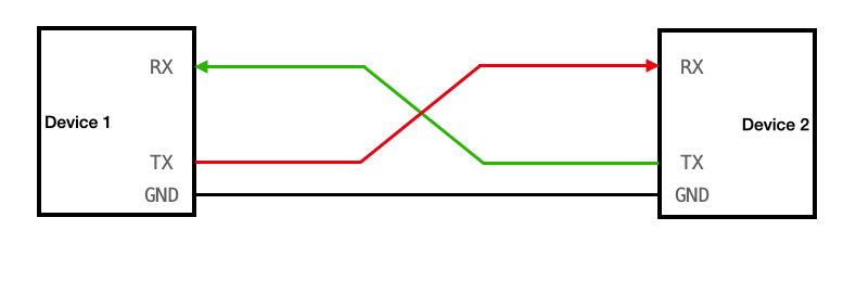
A UART channel has two data lines. There is an RX pin and a TX pin on each device (RX for receive and TX for transmit). Each device’s RX pin is connected to the other device’s TX pin. Note that there are no shared clock lines! This is the “async” aspect of the universal async receiver sender.
As a kind of asynchronous serial communication protocol, UART works by transmitting each binary bit of the transmitted data bit by bit. In the UART communication protocol, when the state on the signal line is high, it represents ‘1’, and when the state on the signal line is low, it represents ‘0’.
For example, when the UART communication protocol is used to transmit one byte of data, eight combinations of high and low levels are generated on the signal line.
- Serial communication refers to the use of a transmission line to sequentially transmit data bit by bit, or two signal lines can be used to form full-duplex communication, such as rs232. The characteristic is that the communication line is simple, the communication can be realized by using a simple cable, the cost is reduced, and it is suitable for the application of long-distance communication, but the transmission speed is slow.
- Asynchronous communication takes one character as the transmission unit. The time interval between two characters in communication is not fixed, but the time interval between two adjacent bits in the same character is fixed. Generally speaking, the clock line is not required for communication between two UART devices. At this time, the same transmission rate, as well as idle bits, start bits, parity bits, and end bits need to be specified on the two UART devices, that is Follow the same protocol.
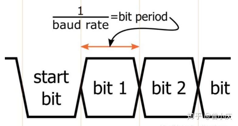
- The data transfer rate is expressed in the baud rate, that is, the number of bits transmitted per second. For example, if the data transmission rate is 120 characters/second, and each character is 10 bits (1 start bit, 7 data bits, 1 check bit, 1 stop bit), then the baud rate of its transmission is 10 ×120 = 1200 characters/second = 1200 baud.
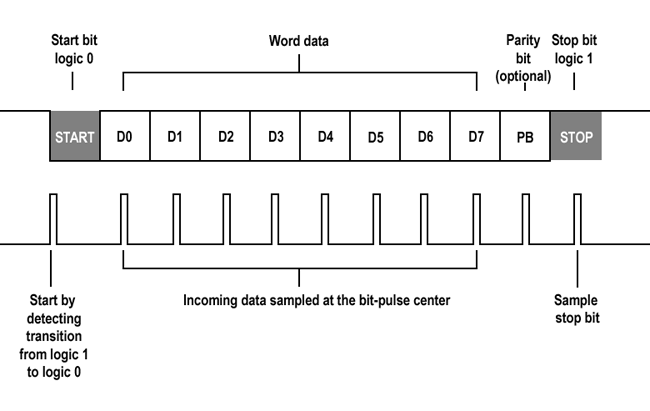
The data communication format is as follows:
Start Bit
Every time a communication starts, the sender sends a logic “0” signal (VOL), indicating the beginning of the transmission character. Because the bus is at a high level when it is idle, a signal that is clearly different from the idle state, that is VOL, is sent first when communication is started.
Data Bit
After the start bit is the data we want to transmit. The data bits can be 5, 6, 7, 8, 9 bits, etc. to form a character (usually 8 bits). Such as ASCII code (7 bits), and extended BCD code (8 bits). The lowest bit is sent first, and the highest bit is sent last. Use a low level to indicate ‘0’ and a high level to indicate ‘1’ to complete the transmission of data bits.
Parity Bit
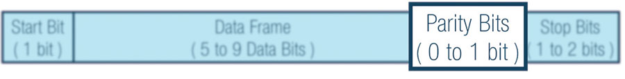
After adding this bit to the data bit, the number of “1” bits should be an even number (even parity) or an odd number (odd parity), so as to verify the correctness of data transmission. The check digit is actually the adjustment number, and the serial port check is divided into several ways:
No Parity
Odd Parity: If the number of “1” in the data bit is an even number, the parity bit is “1”, and if the number of “1” is odd, the parity bit is “0”.
Even Parity: If the number of “1” in the data is an even number, the parity bit is “0”, and if it is an odd number, the parity bit is “1”.
Mark Parity: The check digit is always 1 (not commonly used).
Parity: The parity bit is always 0 (not commonly used).
Stop Bit
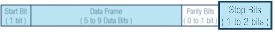
It is an end marker for character data. It can be 1-bit, 1.5-bit, or 2-bit VOH. Since the data is timed on the transmission line, and each device has its own clock, it is likely that there will be a small out-of-sync between the two devices in the communication. So the stop bit not only indicates the end of the transfer but also provides the computer with an opportunity to correct the clock. The more stop bits, the more stable the data transmission, but the slower the data transmission speed.
Protocol layer
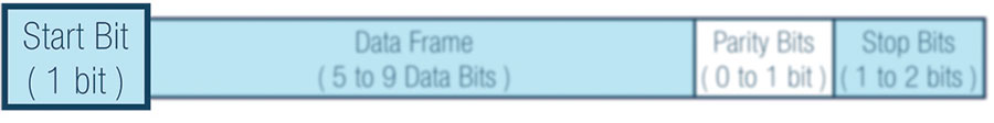
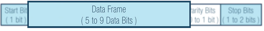
In the protocol layer, the content of the data packet is specified, which consists of a start bit, main data, check bit, and stop bit. The data packet format of both parties must be agreed to be consistent in order to send and receive data normally.
Baud rate
Since there is no clock signal in asynchronous communication, the two communication devices need to agree on a baud rate. Common ones are 4800, 9600, 115200, etc.
Start and stop signals of communication: A data packet of serial communication starts from the start signal and ends with the stop signal. The start signal of the data packet is represented by a data bit of logic 0, and the stop signal of the data packet can be represented by 0.5, 1, 1.5 or 2 data bits of logic 1, as long as the two parties agree.
Data Check: After valid data, there is an optional data check digit. Since data communication is relatively vulnerable to external interference, the transmission data is skewed, and a check digit can be added to the transmission process to solve this problem. The check methods include odd check, even check, 0 check (space), 1 check (mark), and no parity.
Odd parity requires that the number of “1”s in valid data and parity bits is an odd number.
For Example, an 8-bit valid data is 01101001, and there are 4 “1”s in total. If the check bit is “1”, the last transmitted data will be 8 bits of valid data plus 1 bit of check bit, totaling 9 bits. Even parity and odd parity requirements are just the opposite. The number of “1” in the frame data and the parity bit is required to be an even number, such as data frame: 11001010. At this time, the number of “1” in the data frame is 4, so even The parity bit is “0”. 0 check means that the check digit is always “0” no matter what the content of the valid data is, and 1 check means that the check digit is always “1”.
Error States
These are some errors you may encounter when using UART
Framing errors
The UART status and control registers will indicate various status conditions, including transmission-related error states. Understanding this protocol makes it easier to understand error states. They include framing errors, which occur when the receiver does not see a stop bit at the expected bit time. If the data line is not in the expected high state (depending on the number of data and parity bits that set the UART) when the stop bit is expected, the UART will signal a framing error.
Parity error
Parity errors are only raised when the UART is in parity mode. In parity mode, an extra bit is sent to hold the parity (even or odd) of all transmitted data bits. If a data bit is in error (1 for 0 or 0 for 1), the parity bit will be wrong and an error will be thrown specifying the error.
Overrun error
An overflow error occurs when the receiver does not process (deletes a character from the input buffer) until the next character arrives.
Break condition
An interrupt condition is not necessarily an error. This happens when the receiver input is in a logic-low state for more than a certain duration (usually more than one character time). To the receiver, it looks like an all-zero character with a framing error. This is a hack against the software reset circuit. In the python code, you can see that reset is triggered by sending a break. This pulls the data line low long enough for MCLR to be pulled low and the board to reset.
Here’s the difference between UART, I2c, and SPI
| Protocol | Complexity | Speed | # of Devices | # of Wries | Duplex | No. of master and slave | |
| UART | Simple | Slowest | Up to 2 devices | 1 | Full Duplex | Single to Single | |
| I2C | Easy to chain multiple devices | Faster than UART | Up to 127, but gets complex | 2 | Half Duplex | Multiple slaves and master | |
| SPI | Complex as device increases | Fastest | Many, but gets complex | 4 | Full Duplex | 1 master, multiple slaves |
You might be wondering, which of these three communications is the best? Is it UART, I2C, or SPI?
Unfortunately, there is no “best” communication peripheral. Each communication peripheral has its own advantages and disadvantages.
Therefore, users should choose the communication peripherals that best suit their project. For example, if you want the fastest communication peripherals, SPI would be ideal. On the other hand, if the user wants to connect multiple devices without being too complicated, I2C would be ideal as it can connect up to 127 devices and is easy to manage.
Here are Some Product and Expansion borad that supports UART Communication Protocols/ Port
XIAO Series
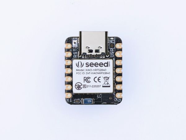
Of, course all the XIAO Series Microcontrollers that support I2C, UART, or SPI, and here’s the link for you to take a look at it Seeed Studio XIAO Series. And now for most of the XIAO Series is Free Shipping!
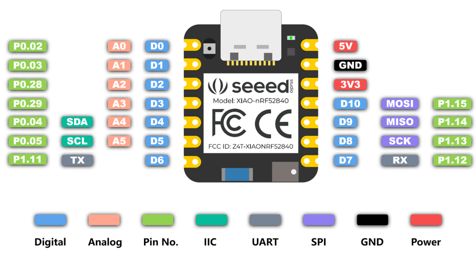
Here are some features of the XIAO Series
- Thumb-sized form factor, only 20×17.5mm. Made for space-constrained scenarios.
- Up to 11 available IOs support multiple interfaces, including analog, digital, IIC, UART, SPI, and more.
- Powerful core with a strong performance for diverse and complex applications.
- Single-sided components, surface mounting design. Easily integrate XIAO into other boards for mass production.
Because XIAO only has limited headers, but you connect other sensors, then you can use XIAO Expansion board at this time. Let you have more unlimited creativity
About Expansino Boards For XIAO
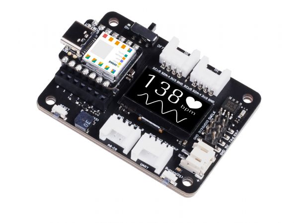
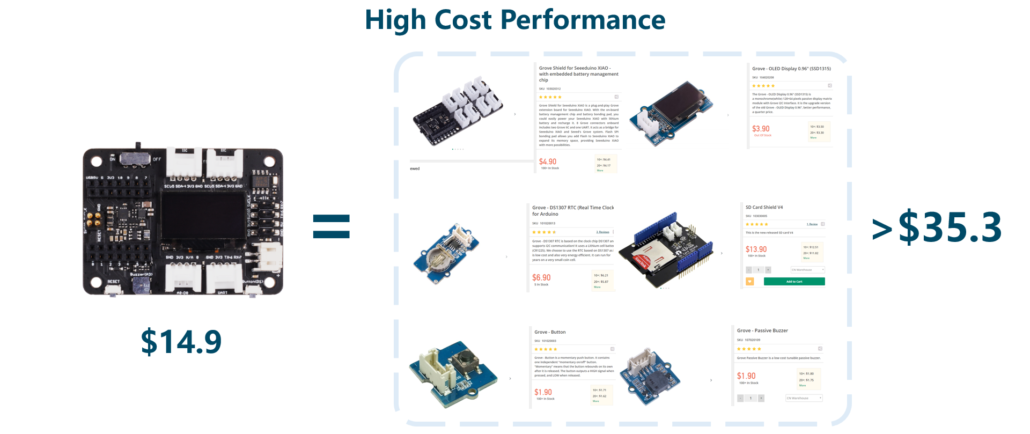
This XIAO Expansino Board has some built-in sensor that you may use in your project like OLED screens, RTC, Buzzer, DIY user Button, SWC and SD card slot on the back. Which can helps you to save some money. And ultra-small size(58 x 42.8mm), smaller than the palm of a hand
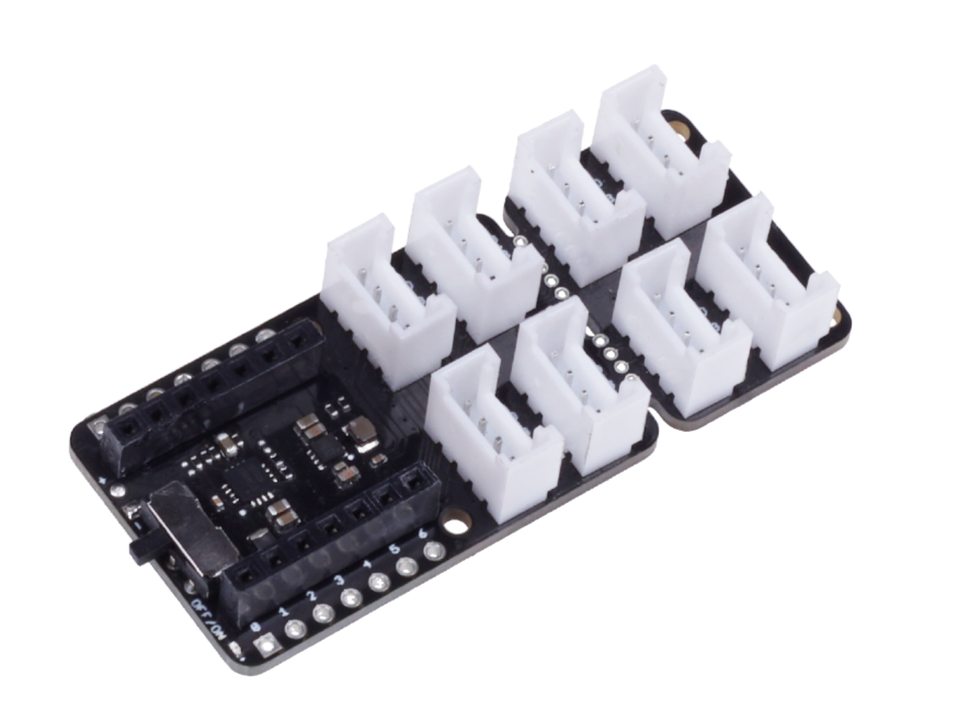
Although the Grove base does not have as many functions as the XIAO Expansion board, it has 4 extra analog/digital port than the XIAO Expansino Board, Which allows you customiz your own board! And the price is cheaper than the XIAO Expansino Board
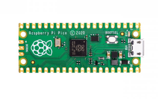
If you want to use a Raspberry Pi product with a UART, the Raspberry Pi Pico is the best choice.
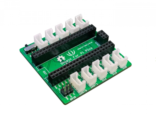
If you feel that the UART, SPI and I2C port of the Raspberry Pi are not enough, then you need a Grove Shield for Pi Pico. The Grove Shield for Pi Pico consists of two I2C and UART port per each, three Digital and Analog port per each, a Power Switch and an SPI and a SWD Debug Interface.
Wio Terminal
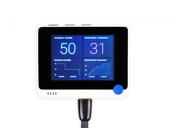
Wio Terminal is an ATSAMD51-based microcontroller with both Bluetooth and Wi-Fi Wireless connectivity powered by Realtek RTL8720DN, compatible with Arduino and MicroPython.
Here are some features of the Wio Terminal
- Powerful MCU: Microchip ATSAMD51P19 with ARM Cortex-M4F core running at 120MHz
- Reliable Wireless Connectivity: Equipped with Realtek RTL8720DN, dual-band 2.4Ghz / 5Ghz Wi-Fi
- Complete system equipped with Screen + Development Board + Input/Output Interface + Enclosure
- Raspberry Pi 40-pin Compatible GPIO enables installation as a peripheral to the Raspberry Pi
- Support Arduino, CircuitPython, Micropython, ArduPy(What is ArduPy?), AT Firmware, Visual Studio Code
- USB OTG Support
At the same time, we also have some Kits for you to take a look at.
Seeed Studio XIAO Starter Kit
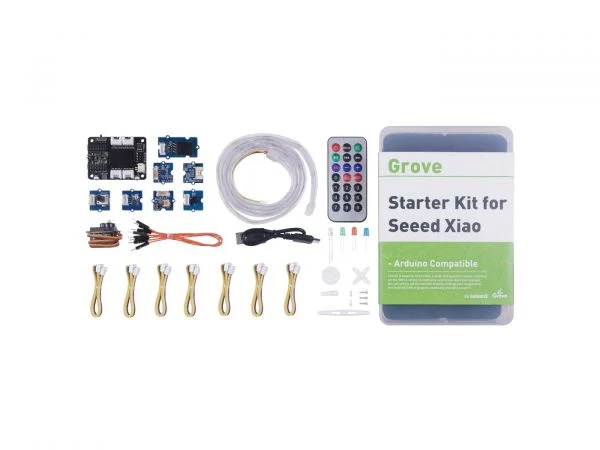
Grove Starter Kit for Seeed Studio XIAO assembles the Seeed Studio XIAO series compatible Expansion board, various kinds of Grove modules, and controllable components in one box, along with free Seeed Studio XIAO Series courses.
Feature for XIAO Starter Kit
- Expand the ability of XIAO Series Dev Board: Compatible XIAO expansion board offers various data transmitting interfaces and functional peripherals
- Support a wide range of application: 9 Grove modules enable environmental sensing, movement detection and mechanical motion control,etc
- Assemble additional controllable components: A 20 key-mini controller, LED Pack with green, red, blue, white that can display a light show
- Attach specific Seeed Studio XIAO Series Courses: Present beginner-friendly courses for quickly getting to know development boards like Seeed Studio XIAO Series and then proceed to realize individual projects
Of course, if you don’t know how to program with Arduino, the K1100 Kit is very suitable for beginners. Just connect the Sensor to Wio Terminal to use it directly
SenseCAP K1100 – The Sensor Prototype Kit
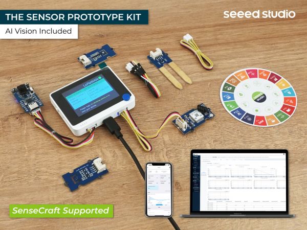
In the digital age where IoT and big data are becoming more prevalent, massive data collection through sensors is required to facilitate digital transformation.
Feature for SenseCAP K1100
- Deploy in 10 Minutes: Build an AIoT project through 3 steps in 10 minutes
- Advanced Technologies: Combination of Machine Learning, LoRa® technology, and pre-trained embedded AI Vision Sensor
- Great Extensibility: Compatible with 400+ Grove sensors to support extensive applications and customization options
- Broad Integration: Compatible with mainstream platforms for Cloud support
- Open-source Platform: Compatible with beginner-friendly programming platforms enabling co-creation of IoT sensors
In this blog, you have learned about the communication protocol of UART and some problems you may encounter when using UART. I hope this article can answer your questions. If you want to know the communication protocol of I2C or SPI, you can check it through this link I2C Communication Protocol and SPI Communication Protocol