Wio Terminal: Arduino Customisable Timer (with Code!)
In today’s article, I will show you how you can transform your Wio Terminal or any Arduino Board with a TFT Display into a customisable kitchen timer!
The Arduino code will be provided at the end, so you can download it as-is to use instantly with your Wio Terminal / Arduino. In addition, I will also be explaining the different sections of code, so that beginners can easily understand and adapt it for their needs!

Intro to the Kitchen Timer Project
You must be wondering – what’s the point of a timer? Aren’t kitchen timer’s really affordable nowadays?
Well, you’re right! But this isn’t any ordinary kitchen timer.
Meet the “Maggie Maker”!

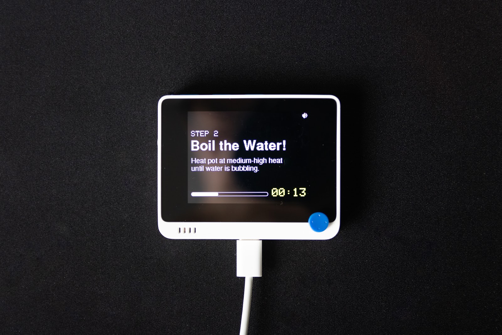
The Maggie Maker is a cookbook / timer all-in-one. By default, I’ve programmed the timer to show you how to make a simple bowl of instant ramen with egg, hence the name (see Wikipedia – Maggi).
Here are some features of the customisable timer:
- Step-by-step instructions for cooking
- Built in timer for instructions that are time-sensitive (like boiling that perfect egg!)
- Toggle-able alarm setting from the main page
Follow today’s tutorial to you can have it working with any Wio Terminal or Arduino with a TFT LCD display in your possession – in no more than 5 minutes! Furthermore, you can customise this timer to display your favourite recipe – and I’ll show you how right now.
How do I Use the Timer?
Even if you have no experience with computer programming, you can simply use the code I’ve written with ease. Just follow these steps!
If you’re not using a Wio Terminal…
The code is written to work with LCD display resolutions of 320×240, but is untested on platforms other than the Wio Terminal. If you have a display with a different size, you may have to tweak the drawings to make some elements display correctly.
We will be using the Wio Terminal’s built in button inputs to control the timer. If you are using another Arduino board, you will require a minimum of two additional buttons to take advantage of the full program functionality. You will also have to reconfigure the input pins in the setup() function of the Arduino code.
1. Download the Arduino IDE
In order to program our Wio Terminal / Arduino board, we are going to use the comprehensive Arduino IDE. First choose the appropriate download for your operating system here.
Then, you can follow the following instructions to get installed: Windows / Mac OSX / Linux
2. Download Timer Code & Install libraries
Next, download the timer code from GitHub as a whole folder. We’re going to need all the files in the repository to let the code work.
If this is the first time you’re using your Wio Terminal, visit the Seeed Wiki page to perform your initial set up.
For other Arduino boards, visit Arduino’s Getting Started page, and select your board from the scrollable navigation panel on the right for your instructions.
Once that’s done, we’re going to install the TFT_eSPI graphics library. This is what allows things to be drawn onto our LCD display.
To install the library, open the library manager in the Arduino IDE and search for “tft_eSPI”. Install the library.

3. Customise Timer Code
Now’s the fun part. Open the MaggieMaker.ino file and scroll all the way to the bottom.
You should see the loop() function shown below (or some variation of it).

You can think of this as a digitalised cookbook. We first have a cover() function, which takes in 0 for the front cover and 1 for the rear.
The front cover() is customisable with two additional String inputs. For example, if you wanted to have it show “How to make pancakes”, you would write:
cover(0, “How To”, “Make Pancakes”);Following this, we have where the magic happens – the page(). The page() function takes in a few parameters in this order:
- Step Number – Displays the step number of the current page.
- Title – This is the main instruction for the page.
- Duration – How long should the timer for this step run for? Enter 0 if no timer is required (eg. preparing or adding ingredients).
- Notes1 – First line of notes. Describe the step or accompanying instructions.
- Notes2 – Second line of notes. Optional input
- Notes3 – Third line of notes. Optional input.
The best thing is that you can add as many pages as you want, so you can really turn this into any kind of cookbook. Have fun with it!
4. Flash to Wio Terminal / Arduino
Once you’re done customising your recipe, we will have to flash it to our Wio Terminal or Arduino board by clicking the arrow button next to the check mark in the Arduino IDE.

For more information, please refer to Step 5 on this page. These instructions will apply to all Arduino boards as well.
If you encounter an error, take a look at what the console says (that’s the black window at the bottom):
If you see “invalid conversion” …
This means that you’ve input the wrong type in the wrong place. Remember that page() takes in 4 compulsory and 2 optional inputs in a specific order! Text inputs should be encapsulated by a “…”, whereas number inputs can be typed plainly.
If you see “expected ‘;’ before” …
This means that you’ve missed out a semicolon! The semicolon or ‘;’ character denotes the end of the line. The IDE should highlight the line that this problem is associated with, so the missing semicolon should be easy to find.
If your code was uploaded successfully but the LCD display is blank …
This can mean that there is a conflict in the TFT_eSPI library that you have installed. To fix the issue, head over to your Arduino/Libraries folder and delete the TFT_eSPI library folder there. Reupload your code and the display should work now!
From this point on, we’re going to get into the implementation!
Platform Introduction: Wio Terminal
If you’ve gotten this far without a Wio Terminal, kudos to you! Because Arduino boards come relatively barebones with no peripherals other than their GPIO pins, you would’ve had to figure out most, if not all, of the hardware configurations.
For this reason, I’ve chosen the Wio Terminal for this project. The Wio Terminal is a fully integrated microcontroller development platform that supports Arduino and MicroPython. It carries Bluetooth, Wi-Fi connectivity, and comes with an LCD screen, onboard IMU, microphone, buzzer, light sensor and infrared emitter.

All I have to do is plug in a common USB Type-C cable, and I can begin writing my code. Not to mention, if I combine it with its battery chassis, I’d already have a mobile kitchen timer form factor – exactly what I needed!
You can pick up a Wio Terminal from the Seeed Online Store.
Cookbook Program Schematic
In this section, I will break down the Arduino code used in the programming. If you haven’t downloaded the project code, you can do so here.
You’ll be able to learn how the code supports the timer’s features – so you can easily make adjustments for your own uses!
However, I won’t be covering the library syntax, so feel free to refer to the following links for their documentation as we go along. You’ll ideally also want to have the full Arduino code by your side, so you know what fits where!
There are 2 main ‘modules’ to the entire Arduino program – the cover() and the page().
Cover()
The cover() function serves two simple purposes – to display the cover text and to allow for the alarm sound to be toggled.
First, we display the text, then enter a while loop that continues when the clicker_state is 0. In this loop, there are multiple “if” statements. Essentially, we are asking the program to continuously check if these buttons are being pressed.
while (clicker_state == 0) {
    // <<ALARM TOGGLE CODE>>
    if (digitalRead(WIO_KEY_C) == LOW) {
        // TOGGLE ALARM
    }
    // BREAK OUT OF LOOP IF BUTTON IS PRESSED
    if (digitalRead(WIO_5S_PRESS) == LOW) {
        clicker_state = 1;
        delay(500);
        alarm_text.deleteSprite();
    }
}
The first condition will toggle between alarm_state 0 and 1, displaying the audio indicator accordingly.
// << ALARM TOGGLE CODE>>
if (digitalRead(WIO_KEY_C) == LOW) {
    if (alarm_state == 1) {
        alarm_state = 0;
        tft.fillRect(300, 0, 50, 50, TFT_BLACK);
        delay(500);
    } else if (alarm_state == 0) {
        alarm_state = 1;
        alarm_logo();
        delay(500);
    }
}
The second condition is waiting for the main button to be pressed, which will set the clicker_state to 1. This will exit the loop and the function ends. The program automatically moves into the following function, which is usually a page().
Page()
The page() function is just slightly more complicated. First, take a look at the schematic.

When page() is called, it immediately creates the sprites for the text to be displayed on the page, then pushes them to be displayed on the LCD. Then, we enter a loop where we await input from the user before proceeding.
If duration is not 0 …
A non-zero duration means that the user wants to engage the timer at this point for the length of <duration> seconds. I created the timer with reference to this Wio Terminal Timer by Seeed on Hackster.

Let’s break down the timer code in detail, since it can be a little overwhelming at first glance.
long start_millis = millis();
int progress, t_min, t_sec;
long seconds_elapsed = 0;
long seconds_remain;

while(seconds_elapsed<duration && clicker_state == 0) {
    seconds_elapsed = (millis() - start_millis)/1000;
    seconds_remain = duration - seconds_elapsed;
    t_min = seconds_remain/60;
    t_sec = seconds_remain%60;


    ttext.setCursor(0, 0);
    ttext.setTextColor(0xFFE0, 0);
    ttext.setTextSize(3);
    ttext.printf("%02d:%02d", t_min, t_sec);
    ttext.pushSprite(220,200);

    progress = 200*seconds_elapsed/duration;
    tft.fillRoundRect(10, 210, progress, 10, 4, TFT_WHITE);

    if (digitalRead(WIO_5S_PRESS) == LOW) {
        clicker_state = 1;
        skipped_timer = true;
    }
}
clicker_state = 0;
Keeping Time:
- Check and record the runtime with millis() before starting the timer and display the empty progress bar.
- Create a while loop to keep checking the time passed, by taking the difference between a new millis() call and the original marked timing.
- Timer stops if clicker_state is 1 or if the timer duration has been completed.
while(seconds_elapsed<duration && clicker_state == 0) {
    seconds_elapsed = (millis() - start_millis)/1000;
    seconds_remain = duration - seconds_elapsed;

    if (digitalRead(WIO_5S_PRESS) == LOW) {
        clicker_state = 1;
        skipped_timer = true;
    }
}
clicker_state = 0;
Displaying Progress:
- Display remaining minutes / seconds by taking the quotient / remainder of the number of seconds remaining divided by 60 respectively.
- Take the proportion of time completed (time elapsed / duration) as the progress bar length / total length. With each loop, redraw a progress bar with the new length to make the bar “move”
t_min = seconds_remain/60;
t_sec = seconds_remain%60;

ttext.setCursor(0, 0);
ttext.setTextColor(0xFFE0, 0);
ttext.setTextSize(3);
ttext.printf("%02d:%02d", t_min, t_sec);
ttext.pushSprite(220,200);

progress = 200*seconds_elapsed/duration;
tft.fillRoundRect(10, 210, progress, 10, 4, TFT_WHITE);
Skipping the Timer:
Conditional statement: If clicker is pressed, assign clicker_state a value of 1 to break out of the while loop on the next iteration.
if (digitalRead(WIO_5S_PRESS) == LOW) {
    clicker_state = 1;
    skipped_timer = true;
}
Ringing the Alarm:
The alarm rings after the time runs out and if alarm_state equals 1. On the other hand, if the timer was interrupted or if alarm_state is 0, the alarm will be skipped.
if (skipped_timer == false && alarm_state == 1) {
    alarm();
} else if (skipped_timer == false && alarm_state == 0) {
    delay(2000);
} else {
    skipped_timer = false;
    delay(500);
}
Finally, A complete page is shown to prompt the user before proceeding to the next step, where the wait for input is implemented with a similar while loop.
If duration is 0 …
A different version of the complete page is simply shown, and the user can click to proceed once they are ready.
Arduino Code: Things to Note
Using the Graphics Library (Drawing, Updating, Erasing)
If you are new to programming LCD displays, I’d recommend you to visit this short 5-minute read on the Seeed Wiki to understand the underlying concepts.
LCD & Sprites
With TFT_eSPI, you can draw directly onto the screen by calling the functions on the LCD class that you’ve defined. However, if you want to draw objects with different text sizes or colours, you will have to specify each parameter with a line in your code. Also, if you want to display multiple copies of the same object, you’ll have to duplicate your lines of code, making it rather messy.
This is where sprites come in. You can think of sprites as secondary displays that are stored in RAM.
Sprites can be written once and pushed multiple times to the LCD – you simply have to define the coordinates for each push. Each sprite will also keep their own defined parameters in memory, so we can avoid the trouble of respecifying our formatting when trying to push multiple sprites consecutively.
If, however, you want to push a different text on the same sprite, you’ll have to call the deleteSprite() function and redraw your sprite from scratch! Else, you may find your new text does not display as desired.
Erasing Screen Content
When working with LCD screens on microcontrollers like Wio Terminal or Arduino boards, you’ll never see the use of an erase function. Instead, we’ll use the sorcery known as covering up our displayed objects with the background colour!
For example, if we want to erase our entire screen that has a background colour of black, we can use:
TFT.fillScreen(TFT_BLACK);Alternatively, we can also draw black, filled rectangles to erase certain sections of our screen, like what I’ve done to erase the timer portion at the bottom of the screen:
TFT.fillRect(0, 200, 400, 40, TFT_BLACK);If you are working with complex sprites and can’t afford to erase by the rectangle-load, simply create a copy of the existing lines of code you already have and change the colour of the elements to your background colour.
For example, the alarm icon is drawn with the following code:
void alarm_logo() {
    sp.createSprite(12,13);
    sp.fillTriangle(5,0,5,13,0,6,0xFFFF);
    sp.fillRect(0,4,2,5,0xFFFF);
    sp.drawFastVLine(8,5,3,0xFFFF);
    sp.drawFastVLine(11,5,3,0xFFFF);
    sp.drawFastVLine(10,3,2,0xFFFF);
    sp.drawFastVLine(10,8,2,0xFFFF);
    sp.drawLine(8,1,10,3,0xFFFF);
    sp.drawLine(8,11,10,9,0xFFFF);
    sp.drawPixel(7,4,0xFFFF);
    sp.drawPixel(7,8,0xFFFF);
    sp.pushSprite(300, 5);
}
To erase it, you can create a counterpart erase_alarm_logo() function with all the components drawn in black, then push it to the same coordinates. The black will overwrite our old sprite on those exact pixels, erasing it neatly!
Non-Blocking Delays & States
One concept I find really worth sharing is the concept of non-blocking delays & state.
We’ve used a lot of while loops in this program, but take note that none of these use the delay() function, at least in the main loop!
Use of delays within loops in microcontroller programming should generally be avoided, especially if we want to “wait” for user input within that loop.
The Problem: Delays
Let’s say we want to flash an LED every second until a user presses a button. We might write the code as follows:
while ( digitalRead(BUTTON_PIN) == LOW ) {
 digitalWrite(LED_PIN, HIGH);
 delay(1000);
 digitalWrite(LED_PIN, LOW);
 delay(1000);
}
Do you see the problem? The ‘button pressed’ condition is only checked for at the beginning of each loop!
Typically, the code in the loop runs so fast that it doesn’t matter. Even if the user pressed the button right after the condition was just checked, the check would quickly come up again as the loop resets – usually occurring even before the button is released!
With delays, that’s only a split second every 2 seconds that the condition is checked! It’s nearly impossible to break out of this loop now.
The Solution: Millis() and State
To avoid the use of delays, we will use the millis() function to keep track of our time. We will also use the LED_on variable to keep track of the LED’s current state.
long currTime = millis();
int LED_on = 0;
Then, we enter our while loop.
while (button_state == 0) {
    if ( (millis() - currTime) > 1000 ) {
        currTime = millis();
        if (LED_on == 0) {
            LED_on = 1;
            digitalWrite(LED_PIN, HIGH);
        } else {
            LED_on = 0;
            digitalWrite(LED_PIN, LOW);
        }
    }
    if (digitalRead(BUTTON_PIN) == HIGH) button_state = 1;
}
When one second has passed, we reset the marker to the current millis() output. If the LED is currently turned off, we’ll turn it on and mark the LED_on state to 1. That way, when the condition is triggered again after 1 second, the LED will be turned off instead.
Now, we no longer have delays in our loop, and you’ll find that this works much more consistently as intended! If you want to read more about non blocking delays and states, I highly recommend you visit this page on the Arduino Forums.
Other Graphics Libraries
The graphics libraries are powerful resources for display graphics on our LCD screens. For this project, I used the TFT_eSPI library, but you can also use LVGL or LovyanGFX. Depending on what you want to draw, you may find some of them better suited for your own projects!
Summary
Phew! Today we’ve looked at the kitchen timer project and how you can use it on your Wio Terminal or Arduino board with LCD display. In addition, I’ve shown you how to customize it without much programming.
We’ve also gone in depth and dissected the program structure and Arduino code, so you can easily change the behaviour of the timer or adapt it for your other programmes!
I hope this tutorial has been helpful for you, and I encourage you to pick up a project of your own – it’s truly the best way to learn!
For more Arduino or Wio Terminal examples, click here.