Analog-to Digital Converter (ADC): Reading Raspberry Pi Analog
Raspberry Pi is a tiny computer that is capable of accomplishing many great projects, thus it’s still the favourite amongst many tinkers and tech enthusiasts. However, even this wonder machine isn’t perfect. Unlike other minicontrollers or MCUs nowadays, Raspberry Pi does not have a built-in Analog-to-Digital Converter (ADC) Circuit.
Therefore, in this article, we will be talking about Analog-to-Digital Converters (ADC) and hopefully, this would aid you in your projects!
What will be covered:
- Overview of Raspberry Pi Analog-to-Digital Converters (ADC)
- Recommendations for Raspberry Pi ADC
- Setting up Raspberry Pi ADC
- Projects with Raspberry ADC
Overview of Raspberry Pi Analog-to-Digital Converters (ADC)
What are ADCs?
ADCs work to convert analog (continuous, infinitely variable) signals to digital (discrete-time, discrete-amplitude) signals.
ADCs are an abbreviation for Analog-to-Digital Converters, they basically convert an analog input into a digital input.

If you’re interested to find out more about Analog and Digital signals, click here!
How do ADCs work?
To understand the concept behind ADCs, need to first know that ADCs follow a sequence when converting analog signals to digital.
There are 2 features to note about ADCs:
Sampling Rate (Frequency)
- Tied to the ADC’s speed.
- Depends on the type of converter and the needed accuracy
- Measured by samples per second.
The equation for sampling rate is:
fs = 1/T
Where,
fs = Sample Rate/Frequency
T = Period of the sample or the time it takes before sampling again.
Resolution
- Determined by its bit length.
- The resolution depends on both the bit length and the reference voltage.
The equation for total resolution is:
Step Size = VRef/N
Where,
Step Size = The resolution of each level in terms of voltage
VRef = The voltage reference (range of voltages)
N = Total level size of ADC.
Why are ADCs necessary?
As mentioned at the start, Raspberry Pi is not capable of reading analog inputs. Thus, ADCs come in handy to convert analog inputs to outputs, which would help the Pi to be analog-friendly.
Interested to get a Raspberry Pi ADC now? Read on as we show you some options that Seeed offers!
Recommendations for Raspberry Pi ADC
After going through some background of ACD, we will now show you the ADCs that’s compatible with Raspberry Pi! Today, we’ll recommend 2 products. Hope that you’ll be able to find one that suits your project!
8-Channel 12-Bit ADC for Raspberry Pi (STM32F030) ($9.90)

This product is an 8-channel ADC based on STM32F030, this is perfect for consumer goods and temperature measurement. It is a cost-effective, low-power ARM Cortex M0 MCU as well!
Features:
- Support Raspberry Pi 3B/3B+/4
- CRC calculation unit
- 5-channel direct memory access(DMA) controller
- Serial wire debug (SWD)
- Calendar RTC with alarm and periodic wakeup from Stop/Standby
- Real-time clock (RTC)
- Timers:
- Advanced-control timer
- General-purpose timers & Basic timers
- Independent and system watchdog timers
- SysTick timer

Later we will be using this ADC to demonstrate how to set up with Raspberry Pi as well!
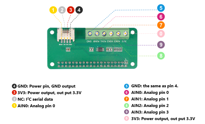
4-Channel 16-Bit ADC for Raspberry Pi (ADS1115) ($10.95)

This product is a 4-channel ADC based on Texas Instrument’s ADS1115, this is perfect for portable instrumentation and battery monitoring etc. It is a compact Raspberry Pi Zero form factor with integrated analog Grove connectors as well!
Features:
- Support Raspberry Pi 3B/3B+/4
- Wide supply voltage range
- I2C-compatible serial interface
- Input multiplexer (MUX) that provides two differential or four single-ended inputs.
- Programmable data rate: 8SPS to 860SPS
- Programmable comparator
- Internal PGA
- Internal low-drift voltage reference
- Internal oscillator
- LOW current consumption:
- Continuous Mode: Only 150μA
- Single-Shot Mode: Auto Shut-Down
Setting up Raspberry Pi ADC
Bought a Raspberry Pi ADC but don’t know how to use it? Don’t fret! We will be showing you how to set up your Raspberry Pi ADC!
What you’ll need:
- Raspberry Pi (3B/3B+/4)
- Channel 12-Bit ADC for Raspberry Pi (STM32F030)
- USB Cable
After you’ve gathered everything you need, you can follow the steps below:
Hardware
Step 1: Insert the 8-Channel 12-Bit ADC for Raspberry Pi into Raspberry Pi
Step 2: Connect the Raspberry Pi to PC through USB cable.
Software
Step 1: Download the source file by cloning the grove.py library.
cd ~
git clone https://github.com/Seeed-Studio/grove.py
Step 2: Install the grove.py library
cd grove.py
# Python2
sudo pip install .
# Python3
sudo pip3 install .
Step 3: Execute the below commands to run the code.
cd grove.py/grove
python adc_8chan_12bit.py
The code below is the adc_8chan_12bit.py code.
import time
from grove.i2c import Bus

ADC_DEFAULT_IIC_ADDR = 0X04

ADC_CHAN_NUM = 8

REG_RAW_DATA_START = 0X10
REG_VOL_START = 0X20
REG_RTO_START = 0X30

REG_SET_ADDR = 0XC0


class Pi_hat_adc():
    def __init__(self,bus_num=1,addr=ADC_DEFAULT_IIC_ADDR):
        self.bus=Bus(bus_num)
        self.addr=addr


    #get all raw adc data,THe max value is 4095,cause it is 12 Bit ADC
    def get_all_adc_raw_data(self):
        array = []
        for i in range(ADC_CHAN_NUM):
            data=self.bus.read_i2c_block_data(self.addr,REG_RAW_DATA_START+i,2)
            val=data[1]<<8|data[0]
            array.append(val)
        return array

    def get_nchan_adc_raw_data(self,n):
        data=self.bus.read_i2c_block_data(self.addr,REG_RAW_DATA_START+n,2)
        val =data[1]<<8|data[0]
        return val
    #get all data with unit mv.
    def get_all_vol_milli_data(self):
        array = []
        for i in range(ADC_CHAN_NUM):
            data=self.bus.read_i2c_block_data(self.addr,REG_VOL_START+i,2)
            val=data[1]<<8|data[0]
            array.append(val)
        return array

    def get_nchan_vol_milli_data(self,n):
        data=self.bus.read_i2c_block_data(self.addr,REG_VOL_START+n,2)
        val =data[1]<<8|data[0]
        return val

    #get all data ratio,unit is 0.1%
    def get_all_ratio_0_1_data(self):
        array = []
        for i in range(ADC_CHAN_NUM):
            data=self.bus.read_i2c_block_data(self.addr,REG_RTO_START+i,2)
            val=data[1]<<8|data[0]
            array.append(val)
        return array

    def get_nchan_ratio_0_1_data(self,n):
        data=self.bus.read_i2c_block_data(self.addr,REG_RTO_START+n,2)
        val =data[1]<<8|data[0]
        return val


ADC = Pi_hat_adc()
def main():
    raw_data=ADC.get_all_adc_raw_data()
    vol_data=ADC.get_all_vol_milli_data()
    ratio_data=ADC.get_all_ratio_0_1_data()
    print("raw data for each channel:(1-8chan)(12 bit-max=4096):")
    print(raw_data)
    print("voltage for each channel:(unit:mv,max=3300mv):")
    print(vol_data)
    print ("ratio for each channel(unit 0.1%,max=100.0%):")
    print(ratio_data)

    print(" ")
    print("NOTICE!!!:")
    print("The default setting of ADC PIN is floating_input.")
    print(" ")

if __name__ == '__main__':
    main()
Now, if there’s no error, it should look like this!
pi@raspberrypi:~/grove.py/grove $ python adc_8chan_12bit.py
raw data for each channel:(1-8chan)(12 bit-max=4096):
[2177, 2098, 2064, 2038, 2127, 2066, 2172, 2145]
voltage for each channel:(unit:mv,max=3300mv):
[1599, 1741, 1668, 1658, 1644, 1787, 1694, 1677]
ratio for each channel(unit 0.1%,max=100.0%):
[521, 544, 514, 504, 500, 559, 524, 505]

NOTICE!!!:
The default setting of ADC PIN is floating_input.
Still uncertain about using a Raspberry Pi ADC? Here’s an example to help you:
What you’ll need (including the items stated just now):
How to connect your hardware:
Step 1: Plug the 8-Channel 12-Bit ADC for Raspberry Pi into Raspberry Pi.
Step 2: Connect the Grove – Sound Sensor to A0 port of the ADC module.
Step 3: Connect the Raspberry Pi to PC through USB cable.
It should look as such:

Software
Tap the following command ++python grove_sound_sensor.py 0++ in the command line interface.
pi@raspberrypi:~/grove.py/grove $ python grove_sound_sensor.py 0
Detecting sound...
Sound value: 433
Sound value: 342
Sound value: 443
Sound value: 300
Sound value: 632
Sound value: 258
Sound value: 591
Sound value: 267
Sound value: 871
^CTraceback (most recent call last):
  File "grove_sound_sensor.py", line 67, in <module>
    main()
  File "grove_sound_sensor.py", line 64, in main
    time.sleep(.3)
KeyboardInterrupt
You can Ctrl + C whenever you wish to quit this program as well. And that is how you set up your Raspberry Pi ADC!
Here are some useful links that would provide more details:
- Datasheet STM32F030
- 8-Channel 12-Bit ADC for Raspberry Pi (STM32F030) Eagle Files
- 8-Channel 12-Bit ADC for Raspberry Pi (STM32F030) Software Library
Projects with Raspberry Pi ADC
After learning how to set up your Raspberry Pi ADC, you’re now ready to explore the sea of projects out there!
Raspberry Pi ADC Tutorial
This tutorial would be useful if you’re still a beginner in Raspberry Pi, it teaches you the basics of Raspberry Pi and the circuits!
What you’ll need:
- Raspberry Pi (any model)
- Channel 12-Bit ADC for Raspberry Pi (STM32F030) (or any Raspberry Pi ADC)
- Connecting pins
- 220Ω or 1KΩresistor (17 pieces)
- 10K pot
- 0.1µF capacitor (2 pieces)
- Bread Board
Want to learn more about this project? Click here!
Interfacing Flex Sensor with Raspberry Pi ADC
Interested to attach an analog sensor to your Raspberry Pi ADC with your Raspberry Pi? This project shows you how to do so!
What you’ll need:
- Raspberry Pi (any model)
- Channel 12-Bit ADC for Raspberry Pi (STM32F030) (or any Raspberry Pi ADC)
- 16*2 LCD display
- Flex Sensor
- Resistors and capacitors
- Breadboard or perf board.
Sounds intriguing? Click here to find out more!
How to Setup a Raspberry Pi Pressure Pad (FSR)

Ever want to make your own pressure pad sensor? Look no further! This project shows you how to detect pressure!
What you’ll need:
- Pressure Pad
- Raspberry Pi (any model)
- Channel 12-Bit ADC for Raspberry Pi (STM32F030) (or any Raspberry Pi ADC)
- Breadboard
- Resistor
- Capacitor
Right up your alley? Click here to learn more!
Summary
And that’s all on Raspberry Pi ADC! Did you learn something new? We covered the basics of ADC, how to set up your Raspberry ADC as well as some fun projects for you to try out! Hope that we’re able to help you find a suitable ADC for your project!
Suggested Readings
Check out the related readings below for more fundamental knowledge!
- What happens in an electric circuit: Voltage vs Current: For voltage, current and everything on electricity.
- Resistors: Pull-up and pull-down resistors: For resistance and what you need to know about resistors.
- Electronics Circuit: Voltage Dividers: For circuits and calculations.
- Introduction to Measuring Instrument: What is a Multimeter?: For multimeter and recommendations on getting one for your projects.