Contactless Temperature Monitor by wio terminal
How to check the temperature with no contact? The project combines PIR detection, IR camera and hand-gesture recognition for perfect safety.
https://www.hackster.io/rei-vilo/contactless-temperature-monitor-6fa25f
Hardware components
Wio Terminal × 1
Grove Gesture Sensor for Arduino (PAJ7620U2) × 1
Grove – mini PIR motion sensor × 1
Grove AMG8833 8×8 Infrared Thermal Temperature Sensor Array × 1
Grove I²C Hub 6 Ports × 1
Story
How to check the temperature with no contact in COVID times? The project combines PIR detection, thermal camera and hand-gesture recognition for perfect safety. An IoT extension allows to operate it remotely.
WARNING — This project is for EDUCATIONAL PURPOSE ONLY and SHALL NOT be used for effective fever detection. Contact your local health authority for appropriate tools and procedures.
How it works
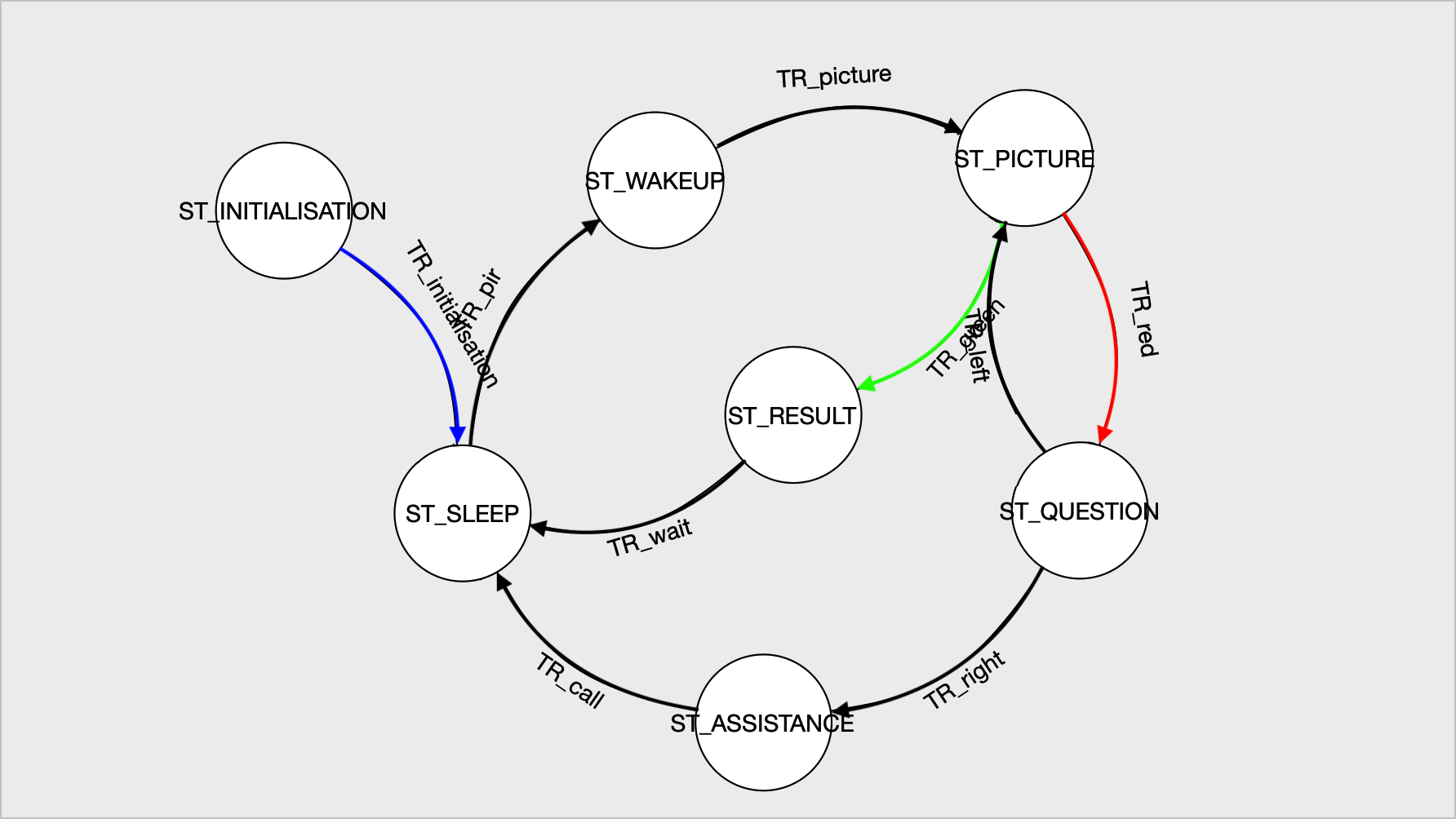
The contactless temperature monitor is built around a finite-state machine and includes seven phases.
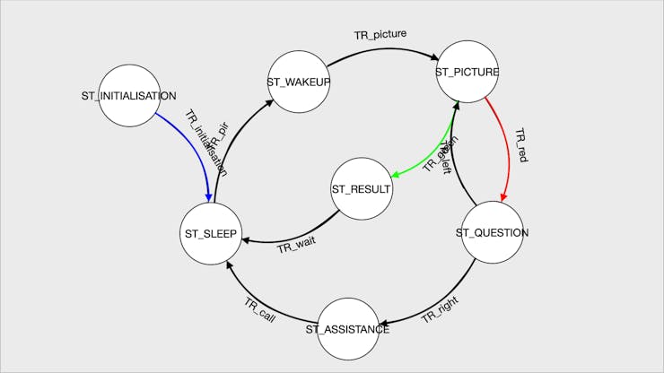
The finite-state machine diagram
- Phase 0: Initialisation
The system initialises the sensors and checks they are operational.
- Phase 1: Sleep
The system is in low-power mode.
- Phase 2: Wake-up
The PIR sensor wakes up the system when it detects a person.
- Phase 3: Takea picture
The IR camera takes a picture and displays it on the screen.
- Phase 4: Result
If no temperature is detected, the person receives a green light.
After a while, the system goes back to sleep.
- Phase 5: Questionand action
Otherwise, a red light shows up and the person is given two options: either take another picture or call for assistance.
The options are displayed on the screen with the corresponding hand gestures: from right to left to take another picture, from left to right to call for assistance.
- Phase 6: Call for assistance
The call for assistance is performed through WiFi.
The system then returns to low-power mode.
Prepare the hardware
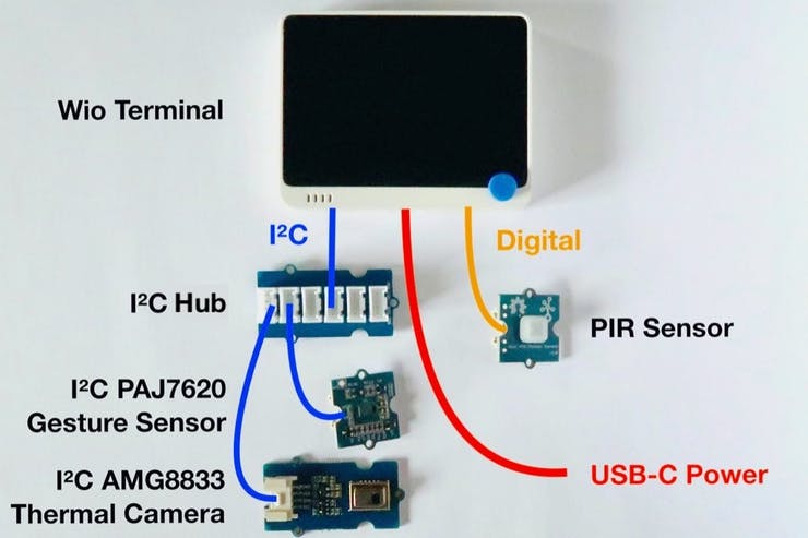
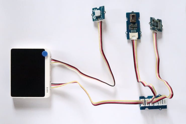
The core of the system is the Wio Terminal. It is ideally suited as it features on a compact white case a powerful MCU, a colour display, and two Grove connectors to attach the sensors.
All the sensors use the Grove connector. It provides a quick, easy and secure way to build whole applications. The IR camera and the hand-gesture sensor go to the I²C Grove connector through the I²C hub. The PIR sensor goes to the GPIO Grove connector.

The Grove connectors are fool-proof and build a circuit in a couple of minutes.
If you’re using the Wio Terminal for the first time, you may need to go through the procedures Get Started with Wio Terminal and Update the Wireless Core Firmware.
- Connect the Grove I²C hub to the Wio Terminal I²C connector.
- Connect the thermal camera and the gesture sensor to Grove I²C hub.
- Connect the IR sensor to the Wio Terminal GPIO connector.
- Finally, connect the Wio Terminal to the computer.
Prepare the software
Although the project relies on the Arduino SDK, I didn’t use the Arduino IDE to develop the project but embedXcode, embedded computing on Xcode, for a better productivity.
Each Grove sensor comes with its library for the Arduino SDK, and so do the screen and the WiFi radio.
The project includes five sub-systems: PIR sensor, LCD display, IR camera, hand-gesture sensor, optional WiFi.
Each sub-system was first tested separately, then integrated to the main project and fully validated before proceeding with the next one.
- Download the attached project.
- Download and install the libraries for each sub-system:
- Screen: Seeed_Arduino_LCD, Adafruit Zero DMA,
- Thermal camera: Seeed-AMG8833,
- Gesture sensor: Gesture-PAJ7620,
- WiFi for MQTT: Seeed-Arduino-FreeRTOS, Seeed_Arduino_atUnified, Seeed-Studio/esp-at-lib, Seeed_Arduino_mbedtls and PubSubClient; optionally Seeed_Arduino_atWiFiClientSecure.
If needed, refer to the procedure How to install library.
- Build and upload the project.
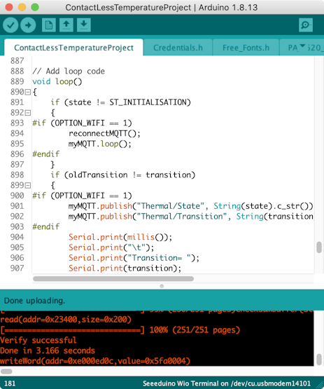
A successful upload
Each sub-system comes with a detailed wiki page: Wio Terminal, Wio Terminal WiFi, Wio Terminal screen, thermal camera, gesture sensor.
The code is very basic as the project is built around a finite-state machine on the loop() function. A C++ library wraps the Gesture-PAJ7620 code as an object for better consistency. The Free_Fonts.h file lists the fonts for the 320×240 screen.
The excellent PubSubClient library provides the MQTT features. The separate file Credentials.h includes the credentials for the IoT extension.
Let’s use it!
- Phase 0: Initialisation
The system initialises the sensors and checks they are operational.

- Phase 1: Sleep
The system is in low-power mode. The screen turns off.
- Phase 2: Wake-up
The PIR sensor wakes up the system when it detects a person.

The screen displays the warning message.
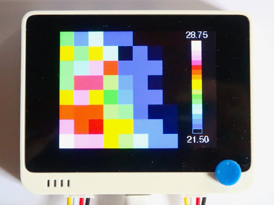
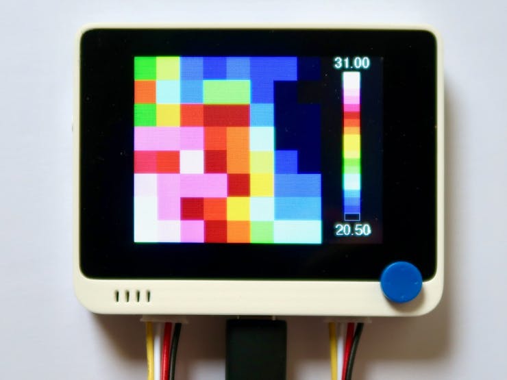
- Phase 3: Take a picture
The IR camera takes pictures and displays them on the screen.

On the right side, the screen displays the scale of colours, with the minimum and maximum temperatures in °C.
- Phase 4: Result
If no temperature is detected, the person receives a green light.
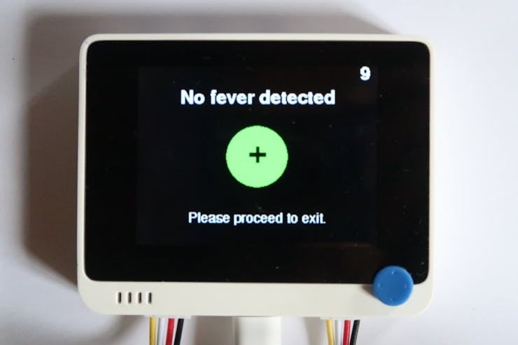
Green light!
After a while, the system goes back to sleep.
- Phase 5: Question and action
Otherwise, there are two cases: either the previous step is inconclusive, or some fever has been detected.
If the previous step is inconclusive, the person is given two options: either take another picture or call for assistance.
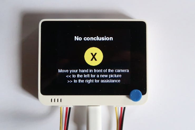
Try again!
If some fever has been detected, the person is also given two options: either take another picture or call for assistance.
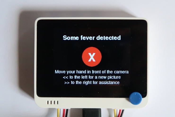
Not so good news
The options are displayed on the screen with the corresponding hand gestures: from right to left to take another picture, from left to right to call for assistance.
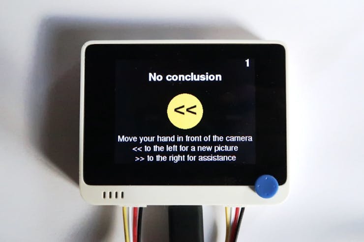
Trying again!
Moving the hand to the left takes another picture.
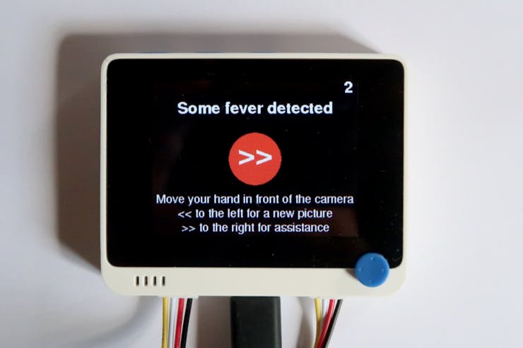
Calling for assistance
Moving the hand to the right calls the assistance.
- Phase 6: Call for assistance
The call for assistance is performed through WiFi.
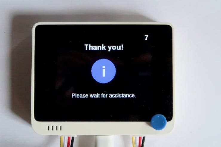
Wait for assistance
The system then returns to low-power mode.
Enable the IoT extension
The IoT extension relies on MQTT to connect to computer with a Node-RED server.
On a computer, for example a single board computer:
- Follow the procedure Getting Started to install Node-RED locally, on a Raspberry Pi or on BeagleBone, on a Docker container, on an Android device.
- Follow the procedure Binary Installation to install the MQTT broker. Binaries are available for Windows, macOS, various flavours of Linux and Raspberry Pi.
- Launch MQTT and Node-RED.
- Install the required node
node-red-dashboard. - Import the Node-RED flow attached and press Deploy.
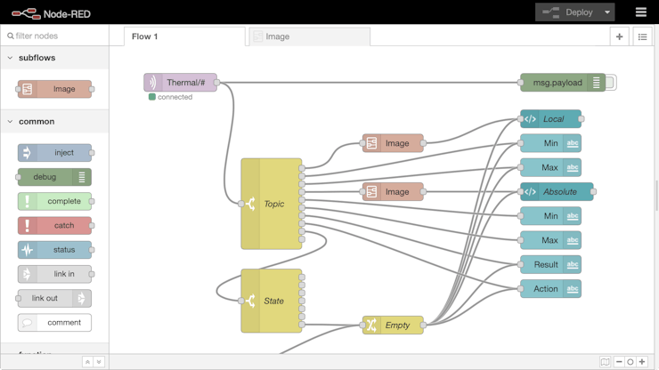
The Node-RED IDE with the flow loaded
- Connect the computer to the WiFi LAN and note the IP address of the computer,
192.168.1.10on the example.
On the Arduino IDE,
- Open the project.
- Ensure the PubSubClient Library: Arduino Client for MQTT is already installed.
For more informations on MQTT, please refer to the excellent project MQTT on Wio Terminal by Salman Faris.
- Edit the credentials file
Credentials.h. - Check
OPTION_WIFIis set to1to activate WiFi.
////// @brief Option for WiFi/// @details 1=activated, 0=desactivated///#define OPTION_WIFI 1- Set the computer IP address
brokerIP.
/// /// @brief IP address of the MQTT broker ///char brokerIP[] = "192.168.1.10";- Enter
ssidWiFiandpasswordWiFito match with your local configuration.
////// @brief Network name = SSID///char ssidWiFi[] = "my network name";////// @brief Network password///char passwordWiFi[] = "my network password";- Build and upload the project.
- On Node-RED, call the menu View > Dashboard to display the dashboard.
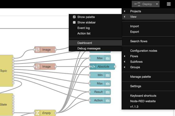
Menu > View > Dashboard
- Click on OK to accept the warning.

The dashboard displays two thermal pictures. On the left, the scale is dynamic with the lowest and highest temperatures to define the range. Here, the highest temperatures is 33.0 °C, which is safe.
On the right, the scale is absolute from 33.0 to 42.5 °C. The threshold is set at 37.5 °C: lime is just below 37.5 °C and yellow just above.
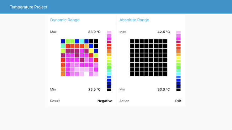
Lime is below 37.5 °C and yellow above.
The two thermal pictures with different ranges and scales help the staff decide what to do.
Below, a positive test performed with a cup of tea. On the screen first:

And then on the dashboard:
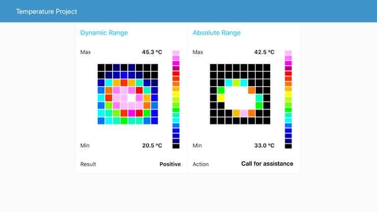
Finally, two more fields give the result and recommended action. When action displays Call for assistance, the person is waiting for the staff.
Improve the local display
By default, the image displayed has the same resolution as the thermal sensor, or 8×8 resolution.
1 / 2 • Initial 8×8 image and…
The initial image is resampled through a bi-cubic interpolation to provide a nicer picture, here in 16×16 resolution.
The FPU of the ATSAMD51 manages all the computations required by the interpolation effortlessly.
Conclusion
The Wio Terminal handles it all: data acquisition and processing, display and WiFi communication with standard MQTT protocol. The Grove connectors are safe and quick to use to connect all the sensors, either I²C or digital.
Below are some ideas to refine the project and add new features.
Going further
The selected IR camera provides a 8×8 matrix with ±2.5°C accuracy. Better resolution and accuracy can be achieved with other Grove thermal cameras like the Grove Thermal Imaging Camera – MLX90621 BAA 16×4 IR Array with 25° FOV (±1°C ±3% accuracy), the Grove – Thermal Imaging Camera – MLX90641 BCA 16×12 IR Array with 110° FOV (±1.5℃ accuracy), or the Grove – Thermal Imaging Camera – MLX90640 32×24 IR Array with 110° FOV (±1.5℃ accuracy).
The entire system can run on batteries with the Wio Terminal Battery Chassis – Built-in 650mAH Lithium Battery with 6 Grove Interfaces.
On the IoT side, the project relies on MQTT and Node-RED with a local router. Other options include adding messages sent from the dashboard to the Wio Terminal screen, using an external MQTT broker like HiveMQ, turning WiFi as an access point to provide a private LAN, relying on other protocols like CoAP and on a third-party service like IFTTT or Blynk.
Also to be considered, an OTA update of the firmware for easier maintenance.
Please remember:
WARNING — This project is for EDUCATIONAL PURPOSE ONLY and SHALL NOT be used for effective fever detection. Contact your local health authority for appropriate tools and procedures.
Schematics
Finite-state machine diagram
The states and transitions of the project

Connections
Use dedicated fool-proof Grove Cables to connect the peripherals to the Wio Terminal.