Top 3 Tips for Dissipating Heat in PCB design
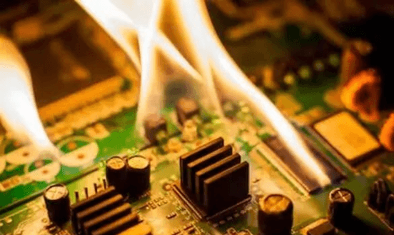
I still remember that in my junior year, my team and I participated in a smart car competition, which required us to design a PCB by ourselves. Just two weeks before we were going to take part in the competition, in the final debugging process of the car, we were surprised to find that the car could not move, which was terrible news for us. After careful inspection, we found that the PCB failed due to localized overheating, which meant that we needed to redesign the PCB and pay more attention to heat dissipation in a short time before the competition. In a word, if a board is not designed to dissipate heat, it could end up with operational problems or even complete failure. Therefore, it’s important to make sure you use adequate PCB heat dissipation techniques in your design. Here are 3 important tips that will help you with your next project.
Tip 1: Add Heat Sinks, Pipes, Cooling Fans or Radiators to High Heat Generating Devices
If a PCB has a few (3 or less) heat generating devices, a heat sink or heat pipe can be added to the heating element. If the temperature cannot be lowered sufficiently, a cooling fan can be useful to enhance the effect of heat dissipation. When the number of heating devices is large (more than 3), a large heat sink (board) can be used, which is a special radiator customized according to the position and height of the heating device on the PCB or a large flat radiator cut out different component height positions. The heat dissipation cover is integrally buckled on the surface of the element, and it is in contact with each element to dissipate heat. However, the heat dissipation effect is not good due to the poor consistency of height during assembly and welding of components. Usually a soft thermal phase change thermal pad is added on the component surface to improve effect of heat dissipation.

Tip 2: Designing the PCB Layout for Effective Heat Distribution
A number of PCB design techniques can be used to control the distribution of heat without additional cost. Here are some tips to bear in mind for your next design:
Temperature-sensitive devices are best placed in the lowest temperature regions (such as the bottom of the device). Never place it directly above the heating device. It is best to stagger multiple devices on the horizontal plane.
Heat sources on the same printed board should be arranged as far as possible to each other according to the degree of heat output. Low heat generating components or parts with low thermal resistance (such as small signal transistors, small integrated circuits, electrolytic capacitors, etc.) can be placed upstream to the cooling fan, while high heat generating devices or devices with high thermal resistance (such as power transistors, large scale integrated circuits, etc.) should be placed downstream of the cooling flow.
Temperature measuring devices should be placed in the hottest region for the most accurate measurement.
The device with the highest power consumption and heat output should be placed where heat dissipation is the most optimal. Do not place high heating devices at corners and edges of the printed board unless there is a heat sink nearby. When designing the power resistor, choose a larger device as much as possible, and allow enough space for heat dissipation when adjusting the layout of the printed board.
The heat dissipation in equipment largely depends on the airflow within the device, so the air circulation should be studied in the design, and the components or printed circuit boards should be properly configured.
In the horizontal direction, high-power devices should be placed as close as possible to the edge of the printed board to shorten the heat transfer path. In the vertical direction, the effect of air reflecting off or being blocked by taller components onto heat sensitive parts should be considered.
For devices that use free convection air cooling, it is preferable to arrange the integrated circuits (or other devices) in longitudinal or transverse order.

Add thermal pads and vias to improve heat conduction and dissipate heat across a larger area. The closer they are to the heat source the better. Vias can be used to conduct heat to ground planes on the other side of the board, which can help distribute heat uniformly over the PCB.
Tip 3: Select PCB Materials and Features for Improved Thermal Conductivity and Distribution
When layout techniques alone cannot fulfil thermal management goals, one may consider more costly solutions. Various PCB materials and features can help dissipate heat on the whole, but may increase the cost considerably or have other influences on the design.
– Standard PCB substrate, FR4, has a very low thermal conductivity. Aluminum PCBs or metal core boards can be considered for high power applications such as those with many high-power LEDs. However, this may limit the PCB design to one layer.
– Increasing the copper weight can help with heat dissipation for high power traces. However, the thicker the copper, the harder it is to achieve tighter trace to trace spacing and trace widths.
– It makes sense that greater volume in vias would help with heat transfer between layers. So, in the past, vias filled with conductive epoxy were popular. However, it provides very little benefit and the high cost of the process is rarely makes it worth it. Regular thermal vias are both free and almost as effective.
In summary, avoid the concentration of hot spots on the PCB, distribute the power evenly on the PCB board as much as possible, and aim to maintain uniform and consistent PCB surface temperature. It is often difficult to achieve strict uniform distribution during the design process, but areas with excessive power density should be avoided. Ultimately, proper thermal management in your design will help you produce a more reliable and economical devices. Seeed has been in the electronics product development and manufacturing industry for more than 10 years and has accumulated a great deal of manufacturing experience. For more design tips and tricks, check out the free Design for Manufacturing manual.