MCP2515 CAN-BUS Arduino Tutorial – Getting started, Interfacing, Applications
If you want to use a microcontroller like your Arduino and its peripheral devices to control your automobile, check out this Arduino CAN BUS tutorial, as we use the MCP2515, CAN-BUS controller module to do that.
Introduction
In today’s time, automobiles have around 60 to 100 sensors units for sensing and exchanging information. With more and more features being added to cars like autonomous driving, airbag systems, smart car systems, sensors units continue to increase.
With sensor units delivering important information like speed and etc, any miscommunication or loss of data could lead to fatal accidents.
Thus, standard communication protocols like UART, I2C, SPI, are not in the equation as they are not as reliable as other communication protocols like the CAN, LIN and FlexRay.
CAN compared to other available protocols is more commonly used and popular.
More about CAN (Controller Area Network) BUS
- CAN which stands for Controller Area Network is used to allow microcontrollers and devices to communicate with each other within a vehicle without a host computer
which allow for control and data acquisition. These devices are also called Electronic Control Units (ECU) and they enable communication between all parts of a vehicle.- ECU in an automotive CAN BUS system can be an energy control unit, airbag, audio system, etc. Today, you can find up to 70 ECUs in a modern car.
- In layman term, the CAN BUS involves a bunch of linked ECUs within a vehicle that communicate with each other based on a broadcast. Every ECU intercepts every broadcast, but individually decide whether or not to react to it.
- CAN is a serial communication bus designed for industrial and automotive applications. For example, they are found in vehicles, farming equipment, industrial environments, etc
- Why not use other communication peripherals like UART, SPI and I2C?
- Well, compared to other communication protocols like UART, SPI and I2C, using CAN BUS communication protocol are much more reliable as they are standard automotive communication protocols that are used to transmit vital data like a throttle position in a vehicle. If miscommunication or loss of data occurs, it could lead to critical failures.
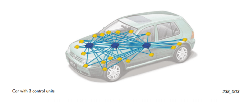
- Without CAN BUS protocol, electronic modules in vehicles will have to communicate with each other using direct, point-to-point analog signal lines. With each module requiring a direct line connected for communication, not only is it time-consuming, it will be messy with all the excessive amount of wiring as seen on the picture above
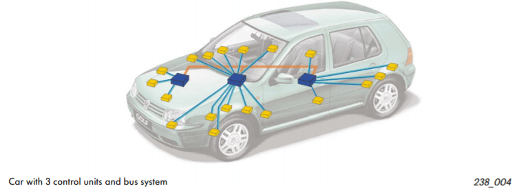
- With CAN BUS protocol, it eliminates the need of all these wiring by enabling electronic devices to communicate with each other with a single multiplex wire that connects each node in the network to the main dashboard as seen on the picture above.
- The multiplex wire and architecture enable signals to be combined and transmitted over the entire network with just a single wire while ensuring each electronic module in vehicles receives data from sensors and actuators. This allows the user to be able to connect any number of ECUs in your vehicle through the two-wire bus.
- It also allows for several features to be added via just software. Furthermore, an ECU is able to use data from another ECU which eliminates the need to install the same sensors in multiple devices.
- With a CAN BUS system, you can now network electronic modules such as control units or intelligent sensors such as the wheel angle sensor.
Want to find out more about CAN BUS? Check out our guide on CAN BUS where you will learn more about CAN protocol, CAN network, CAN message and many more.
Arduino MCP2515 CAN BUS Interface Tutorial
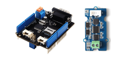
In this tutorial, we will be using Seeed’s CAN-BUS Shield V2.0 which is made up of the MCP2515 CAN Bus controller with SPI interface and MCP2551 CAN transceiver to give your Arduino/Seeeduino CAN-BUS capability.
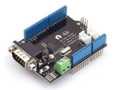
The shield has a CAN controller MCP2515 which is a high speed CAN transceiver. For any beginners and makers, the CAN-BUS Shield V2.0 is perfect for you to enter the world of CAN with its easy connection peripherals.
The CAN BUS Shield works well with Arduino UNO (ATmega328), Arduino Mega (ATmega1280/2560) as well as Arduino Leonardo (ATmega32U4).
Hardware Overview of CAN BUS Shield V2.0
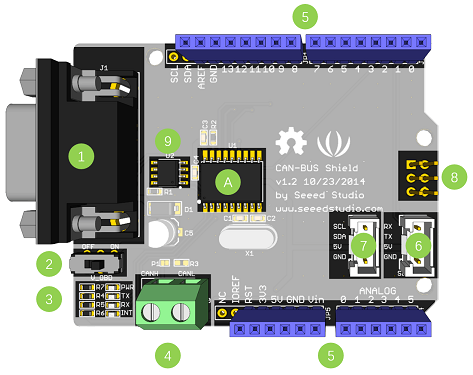
- DB9 Interface – to connect to OBDII Interface via a DBG-OBD Cable.
- V_OBD – It gets power from OBDII Interface (from DB9)
- Led Indicator:
- PWR: power
- TX: blink when the data is sending
- RX: blink when there’s data receiving
- INT: data interrupt
- Terminal – CAN_H and CAN_L
- Arduino UNO pin out
- Serial Grove connector
- I2C Grove connector
- ICSP pins
- IC – MCP2551, a high-speed CAN transceiver (datasheet)
- IC – MCP2515, stand-alone CAN controller with SPI interface (datasheet)
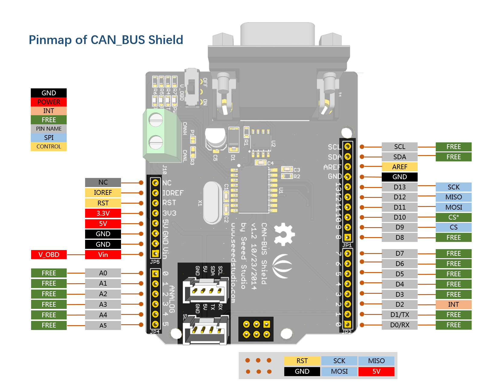
Pin map of CAN BUS Shield V2.0
Without further ado, let us jump right into the tutorial.
What do you need?
- 2 x CAN-BUS Shield
- 2 x Arduino UNO / Seeeduino V4.2
- 2 x Jumper Wire
You will require 2 of each CAN-BUS shield and Arduino as one will act as a transmitter while the other will act as a receiver where communication will happen between them.
Step by Step Tutorial
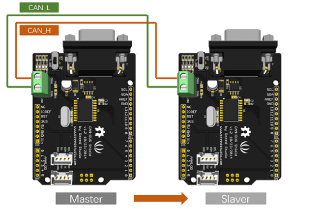
Step 1: Hardware Connection
- Firstly, connect each CAN-BUS shield into Seeeduino V4.2 and connect the 2 CAN-BUS shield together via 2 jumper wires as shown below. (CAN_H to CAN_H and CAN_L to CAN_L)
Step 2: Setting up Software
- Download the library for CAN BUS here and install the library to Arduino IDE after download has completed.
- If you do not know how to install an Arduino library, you can follow the instructions here.
- One of the node (a node means Seeeduino + CAN_BUS Shield) acts as master, the other acts as slaver. The master will send data to slaver constantly.
- Open the send example (File > Examples > CAN_BUS_Shield-master >send) and upload to the master as shown below:

- After that, Open the receive_check example (File > Examples > CAN_BUS_Shield-master > receive_check) and upload to the slaver as shown below

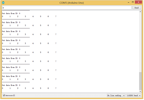
Step 3: View Results
- Open the Serial Monitor of Arduino IDE(slaver), you will get the data sent from the master. Below is a photo of what it will look like:
Step 4: APIs (Application Program Interface)
For the APIs of this software, you can:
Set the Baud Rate
- This function is used to initialize the baud rate of the CAN Bus system. The available baud rates are listed as follows:
#define CAN_5KBPS    1
#define CAN_10KBPS   2
#define CAN_20KBPS   3
#define CAN_25KBPS   4
#define CAN_31K25BPS 5
#define CAN_33KBPS   6
#define CAN_40KBPS   7
#define CAN_50KBPS   8
#define CAN_80KBPS   9
#define CAN_83K3BPS  10
#define CAN_95KBPS   11
#define CAN_100KBPS  12
#define CAN_125KBPS  13
#define CAN_200KBPS  14
#define CAN_250KBPS  15
#define CAN_500KBPS  16
#define CAN_666kbps  17
#define CAN_1000KBPS 18
Set Receive Mask and Filter
- There are 2 receive mask registers and 5 filter registers on the controller chip that guarantee you getting data from the target device. They are useful especially in a large network consisting of numerous nodes.
- We provide two functions for you to utilize these mask and filter registers. They are:
Mask
init_Mask(unsigned char num, unsigned char ext, unsigned char ulData);Filter
init_Filt(unsigned char num, unsigned char ext, unsigned char ulData);- num represents which register to use. You can fill 0 or 1 for mask and 0 to 5 for filter.
- ext represents the status of the frame. 0 means it’s a mask or filter for a standard frame. 1 means it’s for a extended frame.
- ulData represents the content of the mask of filter.
Check Receive
- The MCP2515 can operate in either a polled mode, where the software checks for a received frame, or using additional pins to signal that a frame has been received or transmit completed.
- Use the following function to poll for received frames:
INT8U MCP_CAN::checkReceive(void);The function will return 1 if a frame arrives, and 0 if nothing arrives.
Get CAN ID
- When some data arrive, you can use the following function to get the CAN ID of the “send” node.
INT32U MCP_CAN::getCanId(void)Send Data
CAN.sendMsgBuf(INT8U id, INT8U ext, INT8U len, data_buf);It is a function to send data onto the bus. In which:
- id represents where the data comes from.
- ext represents the status of the frame. ‘0’ means standard frame. ‘1’ means extended frame.
- len represents the length of this frame.
- data_buf is the content of this message.
For example, In the ‘send’ example, we have:
unsigned char stmp[8] = {0, 1, 2, 3, 4, 5, 6, 7};
CAN.sendMsgBuf(0x00, 0, 8, stmp); //send out the message 'stmp' to the bus and tell other devices this is a standard frame from 0x00.
Receive Data
- The following function is used to receive data on the ‘receive’ node:
CAN.readMsgBuf(unsigned char len, unsigned char buf);In conditions that masks and filters have been set. This function can only get frames that meet the requirements of masks and filters.
- len represents the data length.
- buf is where you store the data.
Generate a New BaudRate
We had provided many frequently-used baud rates, as shown below:
#define CAN_5KBPS    1
#define CAN_10KBPS   2
#define CAN_20KBPS   3
#define CAN_25KBPS   4
#define CAN_31KBPS   5
#define CAN_33KBPS   6
#define CAN_40KBPS   7
#define CAN_50KBPS   8
#define CAN_80KBPS   9
#define CAN_83KBPS   10
#define CAN_95KBPS   11
#define CAN_100KBPS  12
#define CAN_125KBPS  13
#define CAN_200KBPS  14
#define CAN_250KBPS  15
#define CAN_500KBPS  16
#define CAN_666KBPS  17
#define CAN_1000KBPS 18
Yet you may still can’t find the rate you want. Here we provide software to help you to calculate the baud rate you need.
Click here to download the software, it’s in Chinese, but it’s easy to use. Here is the interface translated for easier usage:

- Open the software, what you need to do is to set the baud rate you want, and then do some simple setting, then click calculate.
- Then you will get some data, cfg1, cfg2 and cfg3.
- You need to add some code to the library.
- Open mcp_can_dfs.h, you need to add below code at about line 272
#define MCP_16MHz_xxxkBPS_CFG1 (cfg1)    // xxx is the baud rate you need
#define MCP_16MHz_xxxkBPS_CFG2 (cfg2)
#define MCP_16MHz_xxxkBPS_CFG3 (cfg2)- Then let’s go to about line 390, add below code:
#define CAN_xxxKBPS NUM // xxx is the baudrate you need, and NUM is a number, you need to get a different from the other rates.- Open mcp_can.cpp, goto the function mcp2515_configRate(at about line 190), then add below code:
case (CAN_xxxKBPS):
    cfg1 = MCP_16MHz_xxxkBPS_CFG1;
    cfg2 = MCP_16MHz_xxxkBPS_CFG2;
    cfg3 = MCP_16MHz_xxxkBPS_CFG3;
    break;
That’s all! Now, you can use the baud rate you need!
If you want to connect the shield to your automobile, you can check out this OBD>DB9 cable. This cable allows you to connect to an OBD-connector and DB9-connector easier for you to read data and control your car.

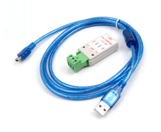
Want to debug your CAN BUS? Check out this USB-CAN Analyzer! With it, you can easily import the acquired CAN-BUS data to your computer for analysis. With the help of the supporting software, you can use this USB-CAN Analyzer to develop, test, manage, and maintain CAN Bus network, as well as receiving, sending, analyzing CAN data.
Alternative CAN BUS module
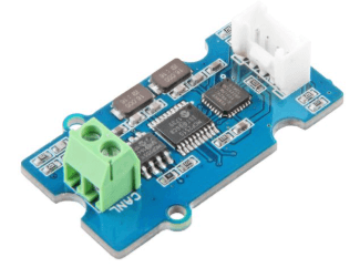
If your project is space limited and also doesn’t need other functions except for CAN-BUS, here is a Grove CAN-BUS module which is Arduino compatible, more compact, and cost-effective. It is also based on the MCP2515 and MCP2551 module.
Other CAN-BUS Products You Can Try
Wio ESP32 CAN Dev Kit

Wio ESP32 CAN Dev Kit is based on the ESP32C3 and uses the Wio-E5 STM32WLE5JC module as the Long Range controller. It supports CAN FD & CAN2.0 communication and features outstanding RF performance and high extensibility. It’s ideal for car hacking and Long Range sensor network management.
This is an upgraded version of the Wio-E5 CAN Dev Kit, it consists of a Wio ESP32 CAN bus Dev Board, an antenna(EU868/US915), a U.FL antenna, and a waterproof case.
Wio-E5 CAN FD Dev Kit

Wio-E5 CAN Development Kit is based on the Wio-E5 STM32WLE5JC Module and supports CAN FD, CAN2.0, and RS485 communication. It supports industrial standards, provides a waterproof case and solar charging interface, and comes with high extensibility and compatibility. It’s ideal for car hacking and Long Range sensor network management.
2-Channel CAN-BUS(FD) Shield for Raspberry Pi

The 2-Channel CAN-BUS(FD) Shield for Raspberry Pi is based on MCP2518 CAN FD Controller and MCP2557 CAN FD Transceiver which communicates with Raspberry Pi via the high-speed SPI interface. It supports CAN FD (CAN with Flexible Data-Rate) protocol is an upgraded version of the traditional CAN BUS that increases the CAN’s transmission rate from 1Mbps to 8Mbps. At the same time, CAN FD improves real-time performance and extends user data frames, providing higher efficiency.
Grove – CAN BUS Module

This Grove – CAN BUS Module based on GD32E103 adopts a brand-new design, uses the cost-effective and high-performance GD32E103 microcontroller as the main control, and cooperates with a firmware we wrote to complete the function of the serial port to CAN FD.
CANBed – Arduino CAN-BUS Development Kit

CANBed – Arduino CAN-BUS Development Kit embeds an ATmega32U4 chip, which means you don’t need to add other jump wires to another Arduino Board, it is an Arduino board itself plus MCP2515 CAN Bus controller and MCP2551 CAN Bus transceiver!
CAN BUS OBD-II RF Dev Kit

CAN BUS OBD-II RF Dev Kit helps you communicate wirelessly with your vehicle’s OBD-II interface using RF (Radio Frequency) through hundreds of meters, which means you can remotely process your vehicle property value data. We also provide tutorials based on Arduino about how you start with it and get data from vehicles.
CAN Bus Car Hacking Kit with Wio Terminal

This CAN Bus Car Hacking Kit provides you with everything you need to hack your car, with a Wio Terminal, an OBD2 connector, and a Grove Serial CAN Bus Module. Almost all modern vehicles have an OBD2 interface. This kit enables you to get all the car information and even control the car through the OBD2 interface. It will be enjoyable for both beginners and experts alike.
OBD-II CAN-BUS Development Kit

This OBD-II CAN-BUS Development Kit is the perfect solution for you to communicate with your vehicle’s OBD-II interface without visiting a mechanic. It includes a Serial CAN Bus module, an OBD-II Connector, and other accessories to help you do all the diagnostics and data logging with ease. We also provide a tutorial which is based on Arduino and you can easily obtain data from your vehicle by following this tutorial.
Applications of CAN
Now you have learnt how to interface a CAN-BUS module with the Arduino, what are some of the applications of CAN?
- Electronic Gear Shift System
- Main Interface in Automation (like industrial)
- Medical Equipment
- Robotics
- Auto Start/Stop of Car Engine
Conclusion
That’s all for today tutorial on MCP2515 CAN-BUS with the Arduino. Hope you learnt something new!
Have questions on CAN or the tutorial? Just leave a comment in the comments down below!