What is a Transistor? Types, Uses, Working Principle
A transistor is defined as a semiconductor device that’s fundamentally built with three terminals for amplifying or switching electronic signals and electrical power purposes. Commonly classified into Bipolar Junction Transistors (BJT), and Field Effect Transistors (FET), these devices allow for the existence of radios, computers, calculators, etc. that you use today.
Well, with modern-day transistors like the BC547, 2n2222, 2n3904, etc. being used in microcontrollers (E.g. Arduino) or electrical circuit building applications, it’s important that we take a deeper look into transistors in today’s blog.
Types of Transistor and its circuit symbols
Earlier, we’ve mentioned that there are two types of transistors; BJTs and FETs. In this section, we’ll dive deeper into each transistor types and explain how it works.
What is BJT (NPN and PNP) and How does it work?
Firstly, for BJTs, it comes in two iterations or versions; NPN and PNP BJT, with its circuit symbols as shown below:

As you can see, both NPN and PNP iterations have pins labeled; Collector (C), Base (B), and emitter (E). The difference between the two can be spotted with the arrow direction; where for NPN, the arrow’s exiting the base while for PNP, the arrow’s entering the base.
How does BJT Work?
Now that we’ve defined what are BJTs, we’ll take a look at how BJTs work with a simple illustration below:
For an NPN transistor, it consists of a layer of P-doped semiconductor between two layers of N-doped material, where electrons are passed from the emitter to the collector instead. The emitter then “emits” electrons into the base, with the base controlling the no. of electrons the emitter emits. The emitted electrons are finally collected by the collector and sent to the following part of a circuit.
Whereas for a PNP transistor, it consists of a layer of N-doped semiconductor between two layers of P-doped material, where the base current entering into the collector is amplified. Essentially, current flow is still controlled by the base but flows in the opposite direction. Additionally, instead of emitting electrons, the emitter in a PNP emits “holes” (a conceptual absence of electrons), which are then collected by the collector.
What is FET and How does it work?
Field-Effect Transistor, the other type of transistor, is most commonly classified as MOSFET (metal-oxide-semiconductor field-effect transistor) and is constructed with pins; Gate, source, drain. With its different pin construction, it works slightly differently as compared to BJTs.
How a FET work
To understand how FET work, we’ll take a look at a typical circuit diagram as follows:
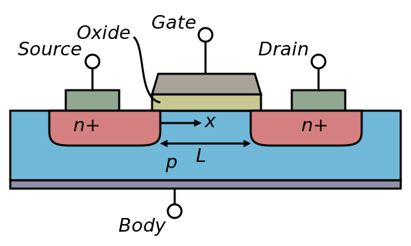
- A block, also known as a substrate of p-type semiconductor acts as the base for MOSFET
- Two sides on this p-type substrate are made highly doped with an n-type impurity (marked as n+)
- The drain terminals (Source and Drain) are then brought out from these two end regions
- The entire surface of the substrate is coated with a layer of silicon dioxide
- Silicon dioxide acts as insulation
- A thin insulated metallic plate is then placed on top of the silicon dioxide, acting as a capacitor plate
- The gate terminal is then brought out from the thin metallic plate
- A DC circuit is then formed by connecting a voltage source between these two n-type regions (marked in red)
When voltage is applied at the gate, it generates an electrical field that changes the width of the channel region, where the electrons flow. The wider the channel region, the better conductivity of a device will be.
BJT vs MOSFET Transistor
Now that we’ve covered both types of transistors; BJT and FET (Commonly known MOSFET), let’s take a look at their differences shown in the table below:
| MOSFET | BJT | |
|---|---|---|
| Definition | Metal oxide semiconductor field-effect transistor | Bipolar Junction Transistor |
| Hardware Construction | 3 terminals: Gate, source, drain with higher structure complexity | 3 terminals: Emitter, base, and collecter |
| Working Principle | For MOSFET to work, it’s dependent on the voltage at the oxide insulated gate electrode | For BJTs to work, it’s dependent on the current at the base terminal |
| Suitability of usage | High power, current control applications Analog and digital circuits | Low-current applications |
Which transistor should you choose?
Although MOSFET holds advantages over BJT such as voltage control, choosing either comes down to your application purposes. Here’s what each transistor are suitable for:
- If you’re looking to regulate the flow of high current in narrow pulses, or for any high power applications, MOSFET is the way to go
- For common electrical circuit usages or low current in-home applications, BJTs may well be sufficient in handling the job
Applications of Transistor
A transistor is most commonly used as either electronic switches in digital circuits or as an amplifier. Let’s explain how each application work.
Transistors as Switches
Switches turn on and off, where for transistors, it acts as such by creating a binary on/off effect of a switch, hence not requiring an actuator for it to flip, but instead voltages. Such an application is used to control the flow of power to another part of a circuit. In other words, a small current flowing through one part of a transistor allows for a much bigger current flow through another part of the transistor.
Transistors as switches can be seen in memory chips, where there are millions of transistors present, switching on and off.
Transistors as Amplifier
Apart from working as switches, transistors work as an amplifier as well, taking tiny electric currents, and producing a much higher current output at the other end. Such transistors are commonly found in products such as hearing aids, radio, or anything from the µV range.
Recommended Transistors for usage
Earlier, we’ve established that MOSFET is part of a FET family, making it a great option for large current flow control. But do you know it’s the first compact transistor that could be miniaturized for a wide range of usages?
Yes! with the revolution in electronics technology, it slowly made its way into miniaturized modules for microcontroller usages (E.g. Arduino)
Below we have a MOSFET transistor recommendation, perfect for such usage!
Grove – MOSFET

As its name suggests, the Grove – MOSFET is a miniaturized MOSFET transistor that helps you easily control a high voltage project with your Arduino board!
It features:
- Two screw terminals on board; one for outer power source, while the other for the device you want control over with
- 5V – 15V voltage control
Thanks to our Grove system as well, you’ll be able to experience plug and play through our Grove cables, easily adding or removing this transistor to your electronic project!
Interested to find out more about the Grove – MOSFET? You can visit its product page here for its datasheet, schematic, and more!
Summary
That’s all for today’s guide on transistors. I hope with this, you get a basic understanding of what is a transistor, transistor types (BJT, FET), How it works, and its applications!
If you’re looking for easy Arduino interfacing with MOSFET, do consider our Grove – MOSFET!