Pull-up Resistor vs Pull-down – Differences, Arduino Guide
Take any digital electronic circuit and chances are you’ll find pull-up and pull-down resistors in them. Well, as for any microcontroller (E.g. Arduino) in an embedded system, it utilizes I/O signals for communication with external hardware devices, where the most commonly known being GPIO. And when there’s nothing connected to your GPIO pins, your program will read a “floating” impedance state, which we do not want. To achieve either “high” or “low” states, we’ll have to implement pull-up or pull-down resistors in our digital circuit.
Hence, in today’s comparison guide, we’ll take a look at what are pull-up and pull-down resistors, its’ differences and an Arduino guide.
- If you wish to find out more about resistors in general, and how to color decode them, you can check out my earlier guide here
What is Pull-up Resistors and it’s purpose

Pull-up resistors are fixed value resistors used between the connection of a voltage supply and a particular pin in a digital logic circuit. More commonly paired with switches, its purpose is to ensure the voltage between Ground and Vcc is actively controlled when the switch is open. Additionally, not affecting the state of the circuit when doing so as well. Do understand that if there aren’t pull-up resistors, it’ll result in a short circuit, which isn’t ideal.
Pull-up resistors applications
- Interfacing device between a switch and a microcontroller board
- Analog to digital convertors,; providing a controlled current flow into a resistive sensor
- I2C protocol bus; allow a single pin to act as an I/P or O/P
When to use pull-up resistors?
If you require a Low default impedance state and wish to pull the signal to “high”, pull up resistors are the ones to use.
What is Pull-down Resistors
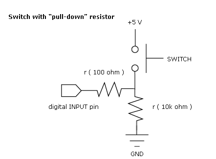
Similarly to pull-up resistors, pull-down resistors ensure the voltage between VCC and a microcontroller pin is actively controlled when the switch is open. However, instead of pulling a pin to a high value, such resistors pull the pin to a low valued instead. Though being less commonly used, a pull-down resistor is still a valid option.
How to calculate values for Pull-up and Pull-down Resistors
With many pull-up or pull-down resistors in digital logic level circuits ranging from 2 to 4.7k, we’ll need to calculate the actual values of these resistors. Similarly to how we calculate resistance for a normal resistor, we’ll use the formula in Ohms law, where R = Voltage/Current or in short, R = V/I
Calculating actual values for pull-up resistors
For pull up resistors, voltage refers to the source voltage minus minimum voltage accepted as high. While the current refers to the maximum current sunk by the logic pins.
Formula for calculating actual value for pull-up resistors:
- R pull-up = (V supply – VH(min)) / Isink
Calculating actual values for pull-down resistors
For pull-down resistors, there’s a slight change to the formula, though it’s still based on Ohms law. Voltage will know be referred to logic Low, while the current refers to the maximum current sourced by the digital pin.
Formula for calculating actual value for pull-down resistors:
- R pull-down = (VL(max) – 0) / Isource
Pull up resistor vs pull down; The Differences
To better illustrate the differences between pull-up and pull-down resistors, I’ll be providing a side-to-side comparison through a table below:
| Pull-Up Resistors | Pull-Down Resistors |
|---|---|
| Connect between I/O pin and +supply voltage, with an open switch connected between I/O and ground. Keeps the input “High” |
Connect between an I/O pin and ground, with an open switch connected between I/O and +Supply. Keeps the input “Low” |
| More commonly used | Less commonly used |
As observed, there aren’t much differences between both type resistors as they share vastly similar functionality.
Arduino Internal Pull-up Resistor Tutorial
The following tutorial demonstrates how you can use INPUT_PULLUP with pinMode(), by monitoring the state of a switch through establishing a serial communication between your Arduino and PC.
Here’s what you need for this tutorial:
- An Arduino Board
- Switch, button, or toggle switch
- Breadboard
- Wires
Hardware Configurations:
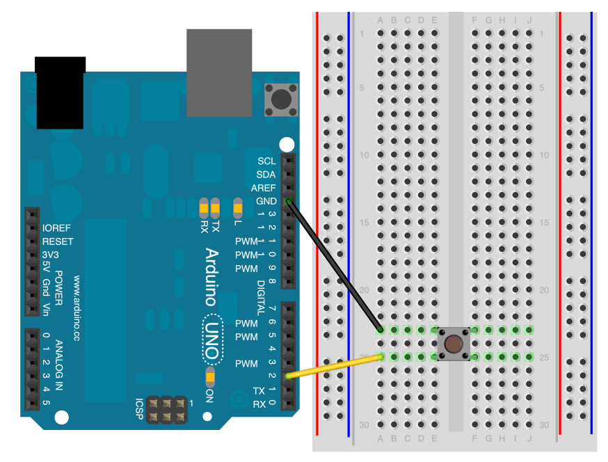
- Connect two wires to the Arduino board
- Black wire connects ground to one leg of the pushbutton
- Second wire connects digital pin 2 to the other leg of the pushbutton
Software Configurations with Arduino Code
- Step 1: Establish 9600 bits of data between your Arduino and your PC by entering the code below:
Serial.begin(9600);- Step 2: Initialize digital pin 2 as an input with the internal pull-up resistor enabled:
pinMode(2,INPUT_PULLUP);- Step 3: Enter the following line, making pin 13, with the onboard LED an output
pinMode(13, OUTPUT);- Step 4: Establish a variable to hold the information coming in from your switch:
int sensorValue = digitalRead(2);- Step 5: Once your Arduino has read the input, make it print this information back to the computer by entering this code:
Serial.println(sensorValue, DEC);Now, when you open your Serial Monitor, you’ll see a stream of “0” if your switch is closed and a stream of “1” if your switch is open. The LED on pin 13 will illuminate when the switch is “High”, and turn of when it’s “Low” as well.
- For the full Arduino code, you can head here
Summary
That’s all for today on pull-up resistors. I hope with today’s blog, you get a deeper understanding of what is a pull-up resistor, the differences between pull-up and pull-down, alongside interfacing with an Arduino board!
- Remember, the key function of a pull-up resistor is to prevent input lines from floating!