How to Use Raspberry Pi GPIO Pins – Python Tutorial
Whether it’s the Raspberry Pi 3, 4 or the tiny Raspberry Pi Zero, GPIO pins have always been a staple feature of our favourite single board computer (SBC), the RPi. However, do you know about its functionality and how to use it to create real world projects? In today’s tutorial, we will show you how to get started with the world of physical computing and GPIO through Python programming!
Today’s Raspberry Pi GPIO tutorial will cover the following:
- What is GPIO and how does it work?
- Explaining the Raspberry Pi GPIO Pinout
- Configuring GPIO pins & Communication Protocols (SPI, I2C)
- Raspberry Pi GPIO Tutorial with Grove & Python
- Raspberry Pi GPIO Projects
What is GPIO and How does it work?
GPIO, short for General Purpose Input Output is a standard interface found on microcontrollers and SBCs that enables digital input and output. It allows these devices to control external components like motors & infrared transmitters (output), as well as to receive data from sensor modules and switches (input). In essence, GPIO allows our Raspberry Pi to interface with a variety of external components, which makes it suitable for a wide variety of projects ranging from a weather station to a self-driving robot.
For GPIO pins to work, software configurations will be required. Fret not, for beginner-friendly Python libraries such as GPIOzero are available to make physical computing more accessible for all users. For more experienced programmers who prefer C or C++, GPIO access libraries such as wiringPI are also available!
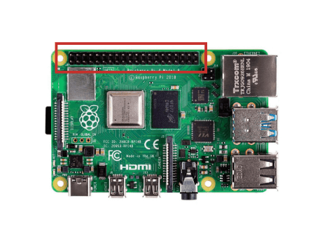
Explaining the Raspberry Pi GPIO Pinout
If you’re using the Raspberry Pi B+, 2 , 3, Zero or the latest Raspberry Pi 4 Model B, you’ll find a total of 40 GPIO pins on your RPi’s GPIO header. Older iterations of the RPI, such as the Raspberry Pi Model B, will only contain a total of 26pins.
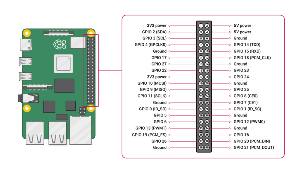
Each of the pins on the 40 Pin header have a designated purpose. The different types are described in the table below.
| GPIO Pin Type | Pin Functionality and Explanation |
|---|---|
| GPIO | GPIO pins are standard general-purpose pins that can be used for turning external devices, such as an LED, on or off. |
| Power | 5V and 3V3 pins are used to supply 5V and 3.3V power to external components. |
| I2C | I2C pins are used for connecting and hardware communication purposes with I2C compatible external modules. |
| SPI | SPI (Serial Peripheral Interface Bus) pins are also used for hardware communication, but with a different protocol. |
| UART | UART (Universal Asynchronous Receiver / Transmitter) pins are used for serial communication. |
| DNC | Use of DNC (Do Not Connect) pins should be avoided. |
| GND | GND (Ground) pins refer to pins that provide electrical grounding in your circuits. |
For more information on the differences between and uses of PWM, I2C, SPI, UART protocols, please refer to the following resources:
- What is Pulse Width Modulation (PWM)? Applications and Accessories
- UART vs I2C vs SPI – Communication Protocols and Uses
- I2C Communication – All about I²C with Diagrams
How to Configure Raspberry Pi GPIO, I2C, and SPI Pins
Now that we know more about the Raspberry Pi’s GPIO, it’s time to get started with physical computing! Similar to other electrical components, we first have to configure the GPIO pins before using them. The configuration guide below will be run on Raspberry Pi OS.
Configuring GPIO
If you’re running the latest version of Raspberry Pi OS, you can skip these steps and get straight into programming with GPIO!
Otherwise, you’ll have to run the following commands in the serial terminal to update your RPI:
sudo apt-get update
sudo apt-get upgrade
If for any reason you don’t have the GPIO package installed, you can run the following command for installation:
sudo apt-get install rpi.gpioConfiguring Raspberry Pi I2C / SPI Pins
To enable I2C or SPI for hardware communication, we’ll use the Raspi-Config tool by entering the following command:
sudo raspi-configIn the menu that shows up, navigate to Advanced Options > I2C and select yes. For SPI, navigate to Advanced Options > SPI instead. Once complete, reboot your RPi and your I2C pins will be enabled. To ensure that I2C communication is working properly with your RPi, connect your modules and enter the command below:
lsmod | grep i2c_For SPI, run the following command instead:
lsmod | grep spi_In each case, the command line should then return a list indicating the modules that you’re running through the I2C / SPI pins.
Essential Products for Raspberry Pi GPIO
Before we move on to how you can program the Raspberry Pi’s GPIO pins with Python, here are some necessities that we recommend.
Grove Base Hat for Raspberry Pi
The Grove Base Hat extends the capabilities of the Raspberry Pi by introducing 15 Grove connectors in addition to the original 40 GPIO pins. Grove is a modular, standardised connector system that allows for quick and convenient electronics prototyping by eliminating the need for jumper wires or solder.
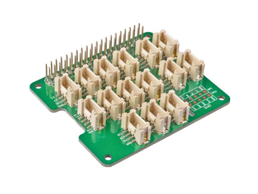
With the Grove Base Hat, the Raspberry Pi gains access to the extensive Grove ecosystem with over 300+ sensors, actuators and communication modules. Thanks to the libraries and detailed documentation that come with Grove, getting started with building projects using Raspberry Pi GPIO has become easier than ever!
Raspberry Pi 40pin to 26pin GPIO Board
If you have older accessories for the Raspberry Pi that were built for the original 26-Pin configuration, this 40-Pin to 26-Pin GPIO conversion board is going to be a true necessity for you.

This GPIO board converts the 40-Pin header on newer Raspberry Pi models into the original 26-Pin layout, so you can continue to use your existing Raspberry Pi accessories. If you’re interested to find out more about this module, please click here.
How to program Raspberry Pi GPIO Pins with Python?
What’s unique of running Python on Raspberry Pi instead of the typical PC is that you can run codes specifically to control hardware components through its GPIO pins! In today’s tutorial, we’ll learn how to use GPIO to blink an LED.
You’ll need the following hardware components:
- Raspberry Pi 4 (4GB / 8GB)
- Grove Base Hat for Raspberry Pi
- Grove – Purple LED (3mm)
Hardware Assembly and Configuration
- Plug the Grove Base Hat into Raspberry Pi
- Select any GPIO port on the Base Hat and connect the Purple LED to it
- Connect the Raspberry Pi to PC through USB cable
For step 2, you can connect it to the Grove Port as well, which would result in the pairing to look like this:

Software Configurations with Python
Step 1: Ensure that your development environment is up to date. This should have been done in our earlier steps.
Step 2: Next, download the source file by cloning the grove.py library with the following commands.
cd ~
git clone https://github.com/Seeed-Studio/grove.py
Step 3: Execute the following command. Take note to replace port_number with the GPIO port number that your LED is connected to.
cd ./grove.py/grove
python grove_led.py port_number
If your port number is 12, your command should look like this:
cd ./grove.py/grove
python grove_led.py 12
That’s it! You should now be able to see the LED blink!
Raspberry Pi GPIO Projects
Now that you’ve seen how easy it is to get started with Raspberry Pi GPIO using Grove, we couldn’t possibly leave you hanging without some project recommendations, could we? With a plethora of projects available thanks to the endless possibilities that GPIO pins offer, I’ll just be providing a few of my favourites today! For a comprehensive list of Raspberry Pi Projects, click here!
1. Raspberry Pi Monitor
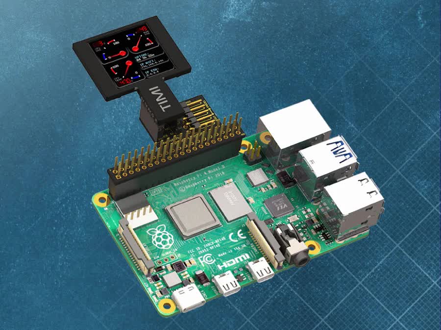
Want to build a helpful monitor that reports real-time CPU performance, temperature, RAM usage, and other useful information using Raspberry Pi.
Hardware & Software Needed
- Raspberry Pi Model 4
- Breadboard Mates TIMI-130
- Breadboard Mates Pi Adaptor
- Breadboard Mates Mates Programmer
- Raspberry Pi OS
- Python3 (built into Raspberry Pi OS)
- Breadboard Mates Studio
Want to know more about this project? Check out the full tutorial on Hackster by Team Breadboard Mates
2. Raspberry Pi Smart Clock

Want to build a smart clock with your Raspberry Pi that shows time on an OLED display? This project not only does that but also reads out the time to you at different intervals! All software configurations are done with Python.
Hardware & Software Needed
- Raspberry Pi 3 Model B
- RGB Diffused Common Cathode
- Speaker: 0.25W, 8 ohms
- Jumper Wires (Generic)
- Raspberry Pi OS on Raspberry Pi
- Python GPIO Library installed on the RPi
- Python SSD OLED Library
Interested to find out more? Visit the full tutorial with Python Code by Ashwini Kumr Sinha on Hackster!
3. Raspberry Pi Driven Robot Arm
This really cool project was developed by our Seeed R&D team. By using the 3D Gesture Tracking Shield that interfaces with the Raspberry Pi via its GPIO header, you can control a robot arm for picking up objects!
Hardware & Software Needed
- Raspberry Pi 3B+
- Seeed 3D Gesture & Tracking Shield for Raspberry Pi (MGC3130)
- Seeed uArm metal
- Raspberry Pi OS on Raspberry Pi
Want to learn more more? Check out the full tutorial by Seeed on Hackster!
4. Smart Raspberry Pi Fan Control
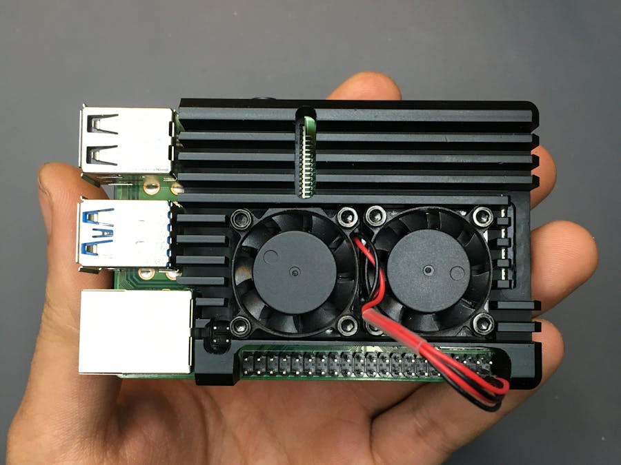
Worry about the thermal issues present in the Rasberry Pi 4, yet only want the fans to turn on when the processor really needs it? This project implements a Python script to adjust fan speeds based on the RPi’s CPU temperatures! Now you can cool your Raspberry Pi and learn Python at the same time!
Hardware & Software Needed
- Raspberry Pi 4 Computer Model B 4GB
- Seeed Armor Aluminum Metal Case with Dual Fans for Raspberry Pi
- General Purpose Transistor NPN
- Resistor 330 ohm
- Breadboard
- Jumper wires
- ThingSpeak API
Interested to find out more? You can check out the full tutorial by Nurgaliyev Shakhizat on Hackster!
Summary
That wraps up today’s guide on how to use the Raspberry Pi’s GPIO PINs with Python! I hope you’ve gotten a better understanding of the different uses of GPIO and how to use it to interface with sensors and modules for building your own electronics projects.
For more Raspberry Pi resources, please visit the following links:
- How To: 3 Methods to Configure Raspberry Pi WiFi
- 28 Raspberry Pi Linux Commands: A Quick Guide to Use the Command Line for Raspberry Pi
- Build a Raspberry Pi Security Camera using Raspberry Pi Camera!
- Build a Raspberry Pi Line Following Robot!
- Top 35 Raspberry Pi 4 Projects That You Must Try Now