ACS712 Current Sensor: Features, How it works, Arduino Guide
Have you ever stopped and wonder the amount of current each of your electrical appliances require? Well, it’s a tedious process to know it all but that’s where the functionality of a current sensor comes to play. With different devices having different current requirements, if a wrong amount of current is fed to them, it may result in severe circumstances (overloading, etc.). Hence, it’s necessary for one to monitor the required current for applications, and that’s when people turn to a current sensor to do the job, notably the ACS712 AC/DC Current sensor.
What is the ACS712 AC/DC Current Sensor?
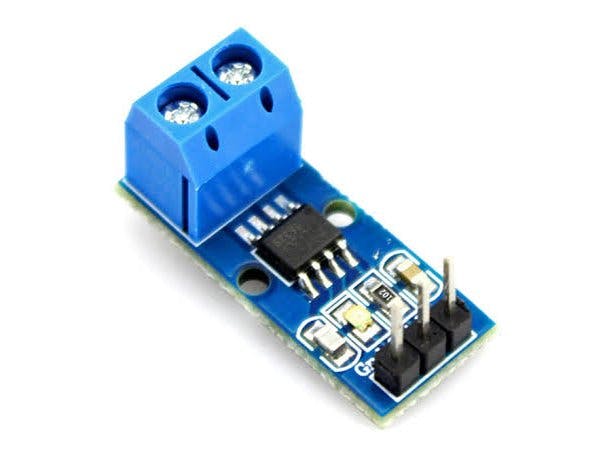
The ACS712 is a fully integrated, hall effect-based linear current sensor with 2.1kVRMS voltage isolation and a integrated low-resistance current conductor. Technical terms aside, it’s simply put forth as a current sensor that uses its conductor to calculate and measure the amount of current applied.
The features of ACS712 include:
- 80kHz bandwith
- 66 to 185 mV/A output sensitivity
- Low-noise analog signal path
- Device bandwith is set via the new FILTER pin
- 1.2 mΩ internal conductor resistance
- Total output error of 1.5% at TA = 25°C
- Stable output offset voltage.
- Near zero magnetic hysteresis
For more information on ACS712 pinout, schematics, and circuit diagram, you can download ACS712 datasheet here!
How does the ACS712 Current Sensor work?
Now that we’ve had an idea of what the ACS712 is capable of, we’ll take a look at its working principle. Well, when it comes to how a current sensor works, it can either be done through direct or indirect sensing. For the ACS712, it uses indirect sensing.
- For current sensors that work by direct sensing, ohm’s law is being applied to measure the drop in voltage when flowing current is detected.
Here’s how the ACS712 work (Simplified):
- Current flows through the onboard hall sensor circuit in its IC
- The hall effect sensor detects the incoming current through its magnetic field generation
- Once detected, the hall effect sensor generates a voltage proportional to its magnetic field that’s then used to measure the amount of current
ACS712 Current Sensor Applications
We’ve established a general idea of what current sensors are applicable for earlier. Well, with the ACS712 IC being able to detect both AC/DC current, it can be used in a wider range of applications apart from electrical appliances. Be it Arduino/other microcontroller usages, or industrial, commercial, and communication applications, it can be found applicable.
Here are the common list of applications:
- Motor speed control in motor control circuits
- Electrical load detection and management
- Switched-mode power supplies (SMPS)
- Protection for over-current
ACS712 Alternatives
Grove – 10A DC Current Sensor (ACS725)

With some users of the ACS712 not recommending it as your current sensor option due to its low sensitivity and bad linearity, we’ve come forth to provide our alternative recommendation; the Grove – 10A DC Current Sensor that’s based on ACS725!
Based on the ACS725, this DC current sensor module is an economical and precise solution to your current sensing needs with capabilities of measuring up to 10A of DC current with a base sensitivity of 264mV/A!
When drawing comparisons to the ACS712, the Grove – 10A DC Current Sensor (ACS725) has the following performance advantages:
- Higher-bandwith; 120KHz compared to 80kHz of the ACS712
- Higher sensitivity; 264mV/A compared to 66 – 185mV/A of the ACS712
- Grove-interface; Easy plug-and-play pairing with your Arduino/Raspberry Pi Board instead of having to solder and use breadboards
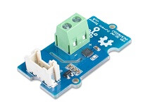
Grove – ±5A DC/AC Current Sensor (ACS70331)

If you’re looking for a current sensor that supports both AC and DC yet retaining performance advantages over the ACS712, the above Grove – ±5A DC/AC Current Sensor (ACS70331) is your pick!
Based on Allegro’s high sensitivity current sensor IC; ACS70331EESATR-005B3, it’s suitable for <5A current sensing applications, alongside its base sensitivty of 200mV/A!
Its features include:
- 1 MHz bandwidth with response time <550 ns
- Low noise: 8 mA(rms) at 1 MHz
- 1.1 mΩ primary conductor resistance results in low power loss
- High DC PSRR enables use with low accuracy power supplies or batteries (3 to 4.5 V operation)
Overall, this AC/DC current sensor module is a superior performing option as compared to ACS712, falling in a similar price range as well. If you would like to find out more about the Grove – ±5A DC/AC Current Sensor (ACS70331), you can check out its product page!
ACS712 Current Sensor Arduino Guide
The ACS712 current sensor can be connected to your Arduino board through a series of jumper wires connections based on its pinout. However, here at Seeed, we understand the complications and complexity of doing so. Hence, we’ve decided to provide a tutorial for our Grove – ±5A DC/AC Current Sensor (ACS70331) to display how easy our Grove plug-and-play system is!
Here’s what you need for today’s tutorial:
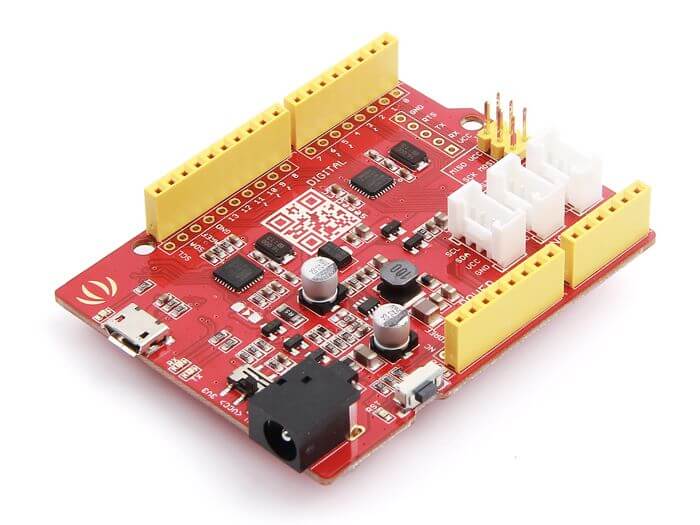
- Seeeduino is Seeed’s very own Arduino board, built with relative benefits over the original
- If you do not wish to purchase a Seeeduino, this tutorial is still applicable for the following Arduino boards: Arduino UNO, Arduino Mega, Arduino Leonardo, Arduino 101, Arduino Due
Hardware Assembly:
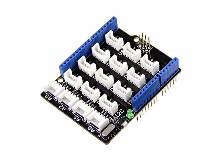
- Step 1: Connect Grove – ±5A DC/AC Current Sensor (ACS70331) to port A0 of the Grove – Base Shield
- Step 2: Connect the positive and negative poles of the circuit to be tested to the corresponding positive and negative poles of the screw terminal
- Step 3: Plug Grove – Base Shield into Seeeduino
- Step 4: Connect Seeeduino to PC via a USB cable
It should look something like this after completing the above steps:

Do note that the above hardware connection is done so with a DC power supply. Do set the current to 0A or do not power on at initial.
Software configurations and Arduino Library
- Step 1: Download the Grove Current Sensor Arduino Library from Github
- Step 2: In the /example/folder, you’ll find the demo code. Here, we’ll take the Grove – ±5A DC/AC Current Sensor (ACS70331) for instance. Click the Grove_5A_DC_Current_Sensor.ino to open the demo or copy the following Arduino code:
#ifdef ARDUINO_SAMD_VARIANT_COMPLIANCE
  #define RefVal 3.3
  #define SERIAL SerialUSB
#else
  #define RefVal 5.0
  #define SERIAL Serial
#endif
//An OLED Display is required here
//use pin A0
#define Pin A5

// Take the average of 500 times

const int averageValue = 500;

long int sensorValue = 0;

float sensitivity = 1000.0 / 200.0; //1000mA per 200mV


float Vref = 1508;

void setup()
{
  SERIAL.begin(9600);
}

void loop()
{
  // Read the value 500 times:
  for (int i = 0; i < averageValue; i++)
  {
    sensorValue += analogRead(Pin);

    // wait 2 milliseconds before the next loop
    delay(2);

  }

  sensorValue = sensorValue / averageValue;


  // The on-board ADC is 10-bits
  // Different power supply will lead to different reference sources
  // example: 2^10 = 1024 -> 5V / 1024 ~= 4.88mV
  //          unitValue= 5.0 / 1024.0*1000 ;
  float unitValue= RefVal / 1024.0*1000 ;
  float voltage = unitValue * sensorValue;

  //When no load,Vref=initialValue
  SERIAL.print("initialValue: ");
  SERIAL.print(voltage);
  SERIAL.println("mV");

  // Calculate the corresponding current
  float current = (voltage - Vref) * sensitivity;

  // Print display voltage (mV)
  // This voltage is the pin voltage corresponding to the current
  /*
  voltage = unitValue * sensorValue-Vref;
  SERIAL.print(voltage);
  SERIAL.println("mV");
  */

  // Print display current (mA)
  SERIAL.print(current);
  SERIAL.println("mA");

  SERIAL.print("\n");

  // Reset the sensorValue for the next reading
  sensorValue = 0;
  // Read it once per second
  delay(1000);
}- Step 3: Upload the demo
- If you’re unsure on how to upload the Arduino code above, do refer to our guide here
- Step 4: Open the serial monitor of your Arduino IDE by clicking on Tool -> Serial Monitor. Set the baud rate to 9600
- Step 5: Calibration
- When there’s no flow of current, the sensor will still produce an output value. This value is called zero offset. Hence, we’ll have to calibrate

- Step 5.1: Set a parameter Vref to fix the value with the following code
float Vref = 1508;
//Vref is zero drift value, you need to change this value to the value you actually measured before using it.
In the demo code, we set the Vref to 1508, however, the zero offset value varies from board to board. Hence we’ll have to modify line 21.
float Vref = 595.70;- Step 5.2: Save the code and upload it again by following step 2 and 3. We’ll now see the outputted value as shown:

So long as the current output becomes to 0mA or a minimal value, calibration is considered completed.
- Step 6: You can now power up the current. Feel free to test it out for yourself, but do note that your current cannot exceed 5A!
For a tutorial on AC load and its respective Arduino Demo code, do refer to our wiki page here!
Summary
Although the ACS712 is a known option when it comes to current sensor modules for Arduino usage, its performance disadvantages as compared to our alternatives here at Seeed are factors to consider!
If you’re looking to get started with current sensing with a AC/DC current sensor, do consider our recommended products:
- For DC current sensing only: Grove – 10A DC Current Sensor (ACS725)
- For both AC/DC current sensing: Grove – ±5A DC/AC Current Sensor (ACS70331)