How to use a Breadboard for Beginners? Wiring, Circuit, Arduino
A breadboard is a solderless construction base used for developing an electronic circuit and wiring for projects with microcontroller boards like Arduino. As common as it seems, it may be daunting when first getting started with using one.
Hence, with today’s breadboard tutorial, I’ll be guiding you on how to use a breadboard, alongside establishing a connection with Arduino.
Before we start with today’s tutorial, let’s learn more about breadboard’s history and the available types.
History of Breadboard


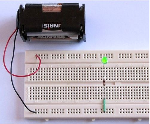
The term “Breadboard” comes from a literal piece of wood used to cut bread, which, back in the early days, people would build electronic circuits on it. A typical circuit is seen in the picture above.
However, with the years of evolution comes design changes. Now, thanks to the invention by Ronald J. Portugal, the breadboard we know comes in a smaller, more portable white plastic and pluggable design.
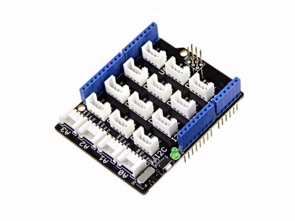
Grove Base Shield can play the role of breadboard while its plug-and-play design enables a more convenient using experience. Grove Base Shield provides a more simple way to connect with Arduino boards and helps you get rid of breadboard and jumper wires! You can directly connect grove sensors to the Base shield through Grove Cables.
Grove is a modular, standardized connector prototyping system. Grove takes a building block approach to assembling electronics. Compared to the jumper or solder-based system, it is easier to connect, experiment, build, and simplify the learning system.
Types of Breadboards?
1. Traditional Breadboard

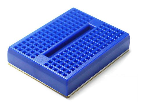
We’ve seen the type of breadboard originating in the past, but the modern-day solderless breadboard comes in different types; full-sized, Full+, half-sized, Half+, and mini.
- With the size difference, there may be variances in how the different rows and columns of wire strips are connected though the general principle should remain the same
- Although the main difference comes in size, there are different shapes and color options available as well
2. Grove Expansion Board
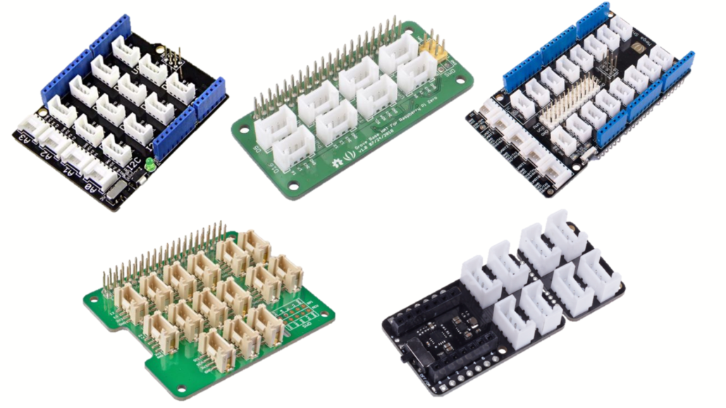
If there’s no Grove connector on your board, you need a Grove Expansion Board to attach the Grove modules. The Grove Expansion Board provides the processing power, and the modules offer your system’s input sensors and output actuators. There are many Grove Expansion Boards for different platforms already, they include Arduino UNO, Particle Phone, BeagleBone board, etc.
Base Shield V2.0 for Arduino ($3.50)
Arduino Uno is the most popular Arduino board so far, however, it is sometimes frustrating when your project requires a lot of sensors or LEDs, and your jumper wires are in a mess. Base Shield provides a simple way to connect with Arduino boards and helps you get rid of breadboard and jumper wires. With the 16 on-board Grove Connectors, you can easily connect with over 300 Grove modules! Apart from the rich Grove connectors on the board, you can also see an RST button, a green LED to indicate power status. The pinout of Base Shield V2 is the same as Arduino Uno R3.
Base Hat for Raspberry Pi Zero ($9.80)
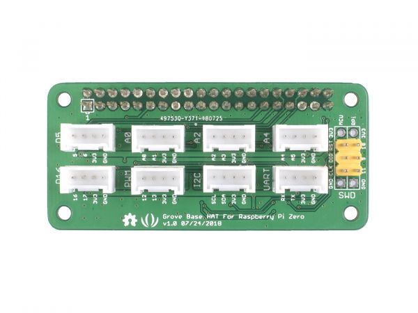
Grove Shield for Raspberry Pi Zero is an expansion board for Raspberry Pi Zero, designed by Seeed Studio, for the orderliness of your connected sensors when you develop projects with Pi Zero. It maintains 24-Pin GPIO and provides 15 additional Grove ports based on the MM32 chip, along with other interfaces, giving you a great and quick development experience.
Mega Shield V1.2 for Arduino and Google ADK ($6.00)
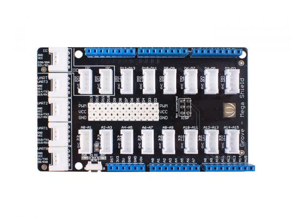
Mega Shield is an extension board for Arduino Mega and Google ADK. We have standardized all the connectors into 4 pins (Signal 1, Signal 2, VCC, and GND) 2mm connectors and kept some of the 3pin (Signal, VCC, and GND) 2.54mm headers for Servo and Electronic Bricks, which simplify the wiring of electronics projects. The 4pins buckled connectors also make the wiring situation more stable. The Mega Shield includes Digital 0 – 21 and Analog 0 – 15; We abandon Digital 22 – 53 for easily installing Mega Shield with Xduino Mega/Google ADK.
Base Hat for Raspberry Pi ($9.99)
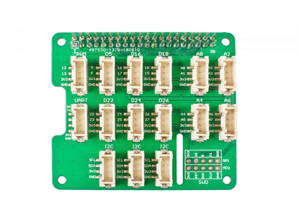
Grove Shield for Raspberry Pi is an expansion board for Raspberry Pi, designed by Seeed Studio, for the orderliness of your connected sensors when you develop projects with Pi. It maintains 24-Pin GPIO and provides 15 additional Grove ports based on the MM32 chip, along with other interfaces, giving you a great and quick development experience.
Shield for Seeed Studio XIAO ($4.50)
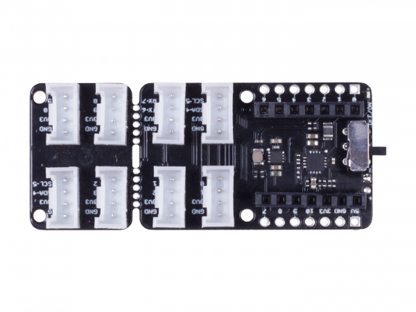
This shield is a plug-and-play Grove extension board for Seeed Studio XIAO. It helps to get rid of jumper wires and soldering work by pulling out the pins of the Seeed Studio XIAO and expanding to 8 Grove connectors, including two Grove IICs and one UART. It acts as a bridge between Seeed Studio XIAO and Seeed’s Grove system, which includes 300+ Grove modules. No more jumper wires and soldering work, you can enjoy creating more projects with Seeed Studio XIAO easily and quickly.
How does a Breadboard work?
When you first lay your hands on a breadboard, you’ll find that there are many pinholes and start to wonder how do I start connecting things? Before you get started, you should learn about the parts and how to power a breadboard.
How is a Breadboard constructed?
1. Bus and Terminal Strips
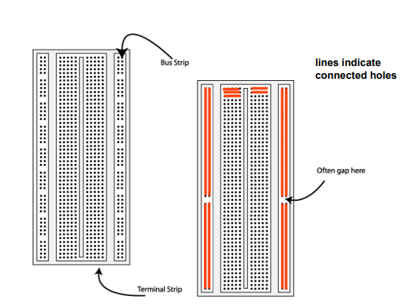
A breadboard consists of two areas called strips: the bus and terminal strip.
- Bus strips are mainly used for power supply connections
- Terminal strips are mainly used for electrical components
- Each strip consists of 5 pinholes, indicating that you only can connect up to 5 components in one particular section
Note: Although each row has 10 pinholes, you can only connect 5 components as the center groove isolates both sides of a given row. This isolation restricts electrical connection between both sides.
How to wire a Breadboard
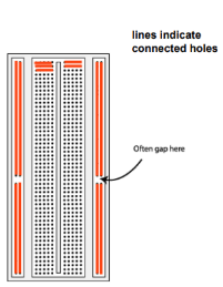
Note how the holes colored in orange are connected together. These sets of connecting holes can be called a node, where it’s possible to interconnect the node from bus strips to terminal strips with jumper wires!
2. Metal Clips


The metal clips are what goes underneath the bus and terminal strips and can be seen when a breadboard is either taken apart or has a transparent outer layer. The function of these metal clips is to grab onto an electronic component when it’s plugged into the pinhole. They are spaced 2.54 mm apart.
*Which electronic component can you use?
- So long as an electronic component has leads or pins, it can be used with a breadboard
- Leads: Long metal legs protruding out of the component
- Pins: Shorter metal legs
3. How to read Breadboard Rows and Columns?
Now that we’ve talked about the breadboard pin functions and what goes underneath it. It is time to explain the labeling on it.
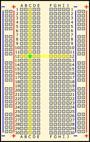
You may have spotted the numbering, letters, and signage written on a breadboard. These are written to help you locate the individual hole in the breadboard, similarly to how finding a cell in an Excel spreadsheet works.
The example as seen above: Hole C12 = Column C, Row 12
What do the “+” and “-” signs mean?

Numbering and letters aside, the positive and negative signs on both sides of the breadboard are power rails, used to power your circuit by connecting the battery pack or external power supply.
There’s no physical difference between positive and negative buses, where labeling is merely for reference and better organization of circuits.
Power Rail Connection
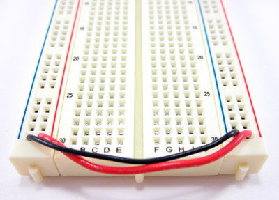
However, as power rails on either side are not connected, you’ll need to connect both sides with jumper wires to establish the same power source on both sides.
Ensure that you connect the positive and negative ends respectively to the right end (positive to positive and negative to negative).
4. Center Groove (DIP Support)
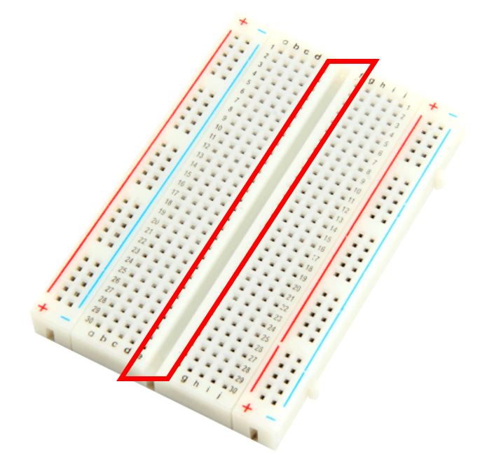
The center groove, also commonly known as the Dual In-line Package (DIP) support, is a groove that runs down the center through the middle of the terminal strips, hence its name. It allows integrated circuits (ICs) to fit onto the breadboard and DIP to be connected in a way that straddles that line.
5. Other Features of a Breadboard
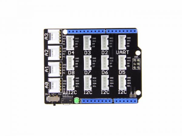
The above components of a breadboard are commonly seen, however, there are other features unique to breadboards, such as the above-mentioned Grove – Base Shield V2.0.

Features:
- On-board Grove port to enable plug-and-play connectivity
- Compatible with over 300+ Grove modules
- On-board reset button
- 4 analog ports, 2 digital ports, 1 UART port, and 4 I2C ports onboard
- Adjustable voltage (3.3V/5V)
How to Power a Breadboard?
When it comes to powering a breadboard, there are plenty of ways to do so. I’ll be recommending the most common ones seen below:
1. Powering through Arduino
If you’re an avid Arduino user, this method would be the simplest for you! Since the Arduino already gets its power from a computer or external power supply, you can simply power a breadboard by “borrowing” its power supply.
Here’s how to power your breadboard through Arduino:
Connect the Arduino GND pin with female headers to the breadboard power rails
- Red wire from the header to the breadboard (+) power rail
- Black wire from the Arduino GND to the breadboard (-) power rail
2. Powering through Batteries
The second way you can power a breadboard is through a battery, a step-by-step tutorial on how to connect an LED on a breadboard using batteries will be shown later!
3. Powering through a Dedicated Power Supply

5V&3.3V Breadboard Power Supply

Similarly to other electronic components, you can power the breadboard directly through our power supply adapter. This 5V & 3.3V breadboard power supply includes a micro-USB port and power jack port, allowing the taking of direct power from a DC wall wart and outputting it in 5V and 3.3V regulated voltage!
Note: Other power supply methods exist, such as binding posts and benchtops. However, these methods are only applicable to certain breadboards and are less commonly used compared to the above 3 ways.
Quick breadboard powering tip!
A general breadboard can handle a power of 5V at 1A, but it’s recommended to keep it below 0.5A/500mA for safety purposes
- Power limits may vary depending on the type of breadboard and its manufacturer. Do check the datasheet/specifications of the breadboard before purchasing one!
How to build a Simple Breadboard Circuit?
Earlier, we understood the principle of breadboard but now comes to the part where you start building your first breadboard circuit! I’ve provided a tutorial for both beginners and Arduino users to try!
Establishing a Breadboard Circuit Connection
Before we move on to an actual breadboard circuit tutorial with LED, here are 3 crucial steps you need to first know in establishing a breadboard circuit connection with resistors and power supply
Step 1: Connect one of the power supply terminals to a hole of any section on the breadboard
Step 2: Connect one terminal of a resistor to the hole of that section such that both devices are connected to each other
Step 3: Take another resistor and connect it to the hole of another section. Connect the second power supply terminal to that same hole
Breadboard Circuit Tutorial
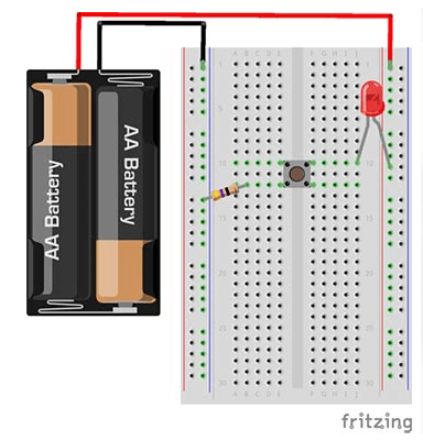
Now that you’ve understood how to establish a simple breadboard circuit connection, here’s a tutorial from Starting Electronics to help you get started with building a breadboard circuit with LEDs!
Here’s what you need:
- 1 A resistor from our Resistor Pack
- 1 5mm LED
- A Battery pack or a Battery Case with 2 AA batteries
- 1 Pushbutton
Step 1: Insert the LED into the breadboard
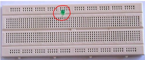
Plug the LED’s longer lead (anode) into the breadboard’s top rail and the shorter lead (cathode) into a hole in the main part of the breadboard.
Step 2: Insert the Resistor into the breadboard
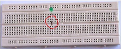
Plug one of the leads of the resistor into a hole directly below the cathode lead of the LED and the other lead into a hole below the middle channel of the breadboard. This connects the LED cathode to one of the resistor leads. It does not matter which way the resistor is plugged into the breadboard.
Step 3: Insert the wire link into the breadboard
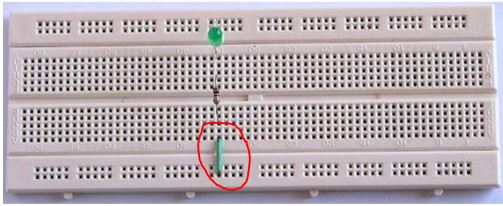
Insert a wire connector into a hole directly below the resistor lead and into the bottom rail of the breadboard
Step 4: Insert the battery into the breadboard
Plug the battery’s red wire (+) into the top rail and the black wire (-) into the bottom rail.
An Electrical circuit should now be formed, with the LED lighting up.
Note: You can completely rearrange the layout of the circuit but following the breadboard diagram exactly is the easiest way to get started with building a breadboard circuit.
Bonus! Want to build a breadboard circuit without buying a physical product?
If you wish to learn and build your own circuits without buying an actual breadboard, you can use Fritzing, a free software program allowing you to build a breadboard circuit without physically getting one!
Besides, if you are looking to learn electronics, design & build circuits, go to Electronics tutorials for self-learning. They have compiled a list of the best resources that can help with your learning.
Common Mistakes while connecting a Breadboard
- Getting Row numbers wrong
- Getting power and ground mixed up
- Red = Positive (+)
- Black = Negative (-)
- Not pushing leads & wires all the way in
- Leads need to be firmly and fully in the breadboard
- Putting components backward
- Polarity (positive to positive, negative to negative)
- Short Circuits
- Leads bumping into each other
How to build a breadboard circuit with Arduino?
Arduino Breadboard Tutorial with LED and Water Level Sensor
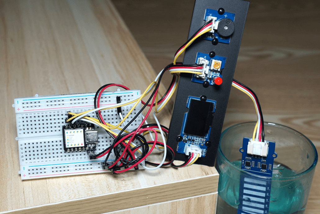
For this Arduino breadboard tutorial, we’ll be sensing water level using the XIAO SAMD21, the smallest Arduino board in the Seeeduino Family that’s packed with SAMD21G18 and applicable for breadboard usage!
Hardware Components Needed:
- 1 XIAO SAMD21
- 1 Breadboard
- 4 4-pin Male Jumper to Grove 4-pin conversion cable
- 2 Dupont Jumper Wires
- 1 Grove – LED Pack
- 1 Grove – Buzzer
- 1 Grove – Water Level Sensor (10cm)
- 1 Grove – OLED Display 0.96″
Hardware Assembly and Configurations:
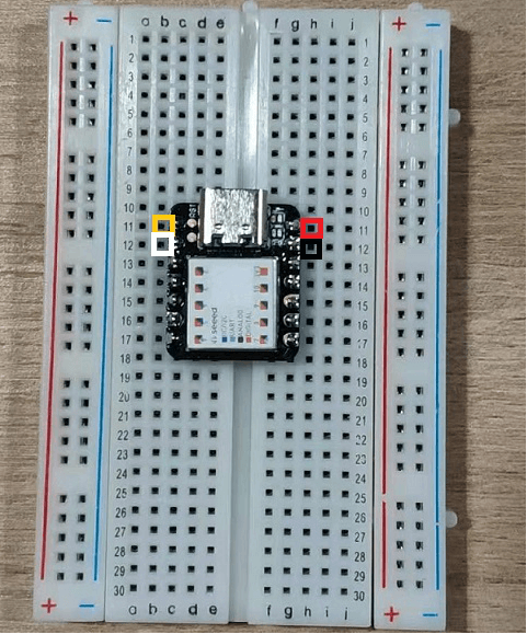
Step 1: Insert the XIAO SAMD21 into the breadboard, and reserve the wiring positions on both sides. The row of each pin on the left and right is connected

Step 2: Connect the 4-pin Male Jumper to Grove 4-pin Conversion Cable with Grove – Water Lever Sensor
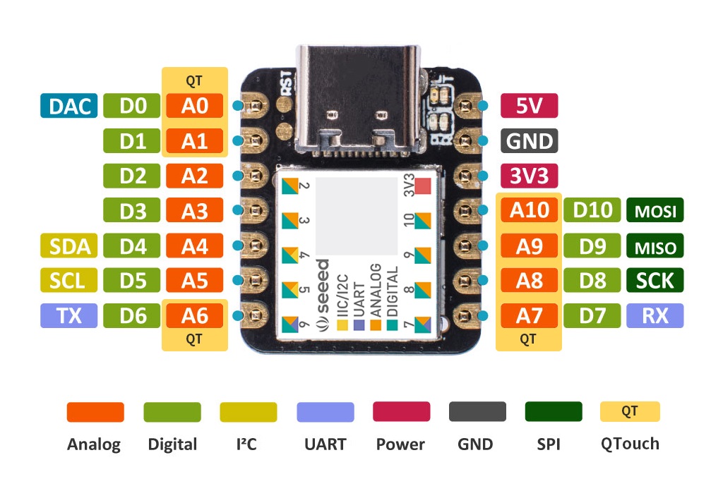
Based on the pinout above, connect the jumper side as follows:
| RED | 5V |
| BLACK | GND |
| WHITE | A0 |
| YELLOW | A1 |
The Grove side of the cable is then connected to the Grove – Water Level Sensor.
Step 3: Use the 4-pin male jumper to Grove 4-pin conversion cable and connect to OLED Display 0.96″. Since the Seeeduino Xiao is an I2C interface, SDA and SCL are used
Connect the jumper side as follows:
| RED | 5V |
| BLACK | GND |
| WHITE | SDA |
| YELLOW | SCL |

The Grove side of the cable is then connected to the OLED Display 0.96″.
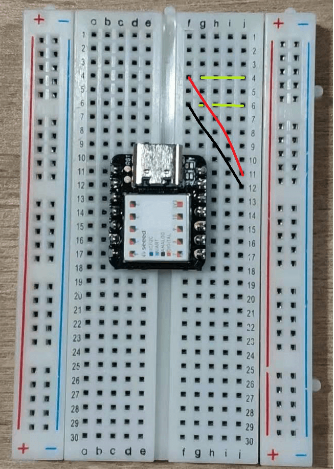
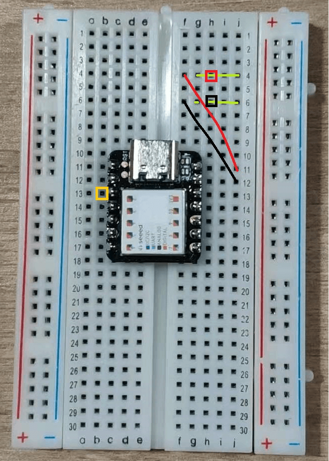
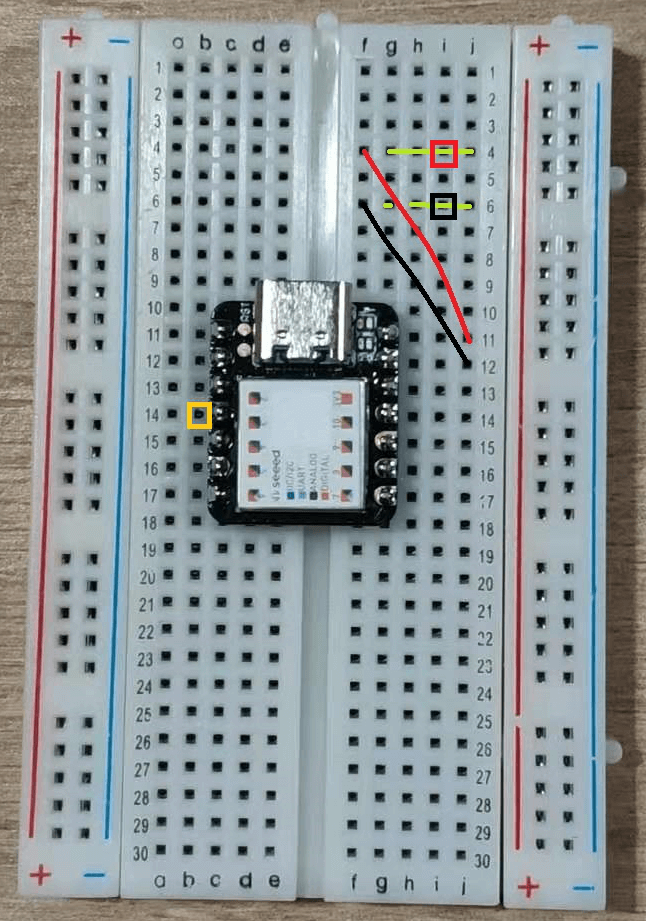
Step 4: Use the 4-pin Male Jumper to Grove 4-Pin conversion cable to connect LED using the D2 interface, but since there’s only one interface left in each row of 5V and GND, we’ll have to lead the line out so that subsequent components can be used.
Use the Red and Black wires to lead it to the position shown in the figure with
- The yellow line in the fourth row are all connected to 5V
- The jacks covered by the yellow line in the sixth row are all connected to GND
Now the lines are connected by:
| RED | Newly connected 5V |
| BLACK | Newly connected GND |
| YELLOW | D2 |
| WHITE | Not Connected |
The Grove side of the cable is then connected to the LED pack.
Step 5: Use the 4-Pin Male Jumper to 4-Pin Conversion Cable to connect the Buzzer using the A3 port.
The end of the jumper wire is connected as follows:
| RED | Newly connected 5V |
| BLACK | Newly connected GND |
| YELLOW | A3 |
| WHITE | Not Connected |
The Grove side of the cable is then connected to the Buzzer.
Step 6: Connect the Seeeduino Xiao to your PC via a Type-C cable
Software Configurations and Arduino Code:
Step 1: Open up Arduino IDE, copy the following code and upload the code
If you’re unsure of how to upload the code, refer to our guide here
#include <Wire.h>
#include <Arduino.h>
#include <U8x8lib.h>

U8X8_SSD1306_128X64_NONAME_SW_I2C u8x8(/* clock=*/ A0, /* data=*/ A1, /* reset=*/ U8X8_PIN_NONE);         // Digispark ATTiny85

#ifdef ARDUINO_SAMD_VARIANT_COMPLIANCE
#define SERIAL SerialUSB
#else
#define SERIAL Serial
#endif

const int ledPin = 2;
const int buzzerPin = 3;
int value = 0;


unsigned char low_data[8] = {0};
unsigned char high_data[12] = {0};


#define NO_TOUCH       0xFE
#define THRESHOLD      100

#define ATTINY1_HIGH_ADDR   0x78
#define ATTINY2_LOW_ADDR   0x77


void getHigh12SectionValue(void)
{
  memset(high_data, 0, sizeof(high_data));
  Wire.requestFrom(ATTINY1_HIGH_ADDR, 12);
  while (12 != Wire.available());

  for (int i = 0; i < 12; i++) {
    high_data[i] = Wire.read();
  }

  delay(10);
}


void getLow8SectionValue(void)
{
  memset(low_data, 0, sizeof(low_data));
  Wire.requestFrom(ATTINY2_LOW_ADDR, 8);
  while (8 != Wire.available());

  for (int i = 0; i < 8 ; i++) {
    low_data[i] = Wire.read(); // receive a byte as character
  }


  delay(10);
}


void check()
{


  int sensorvalue_min = 250;
  int sensorvalue_max = 255;
  int low_count = 0;
  int high_count = 0;
  while (1)
  {
    uint32_t touch_val = 0;
    uint8_t trig_section = 0;
    low_count = 0;
    high_count = 0;
    getLow8SectionValue();
    getHigh12SectionValue();

    Serial.println("low 8 sections value = ");
    for (int i = 0; i < 8; i++)
    {
      Serial.print(low_data[i]);
      Serial.print(".");
      if (low_data[i] >= sensorvalue_min && low_data[i] <= sensorvalue_max)
      {
        low_count++;
      }
      if (low_count == 8)
      {
        Serial.print("      ");
        Serial.print("PASS");
      }
    }
    Serial.println("  ");
    Serial.println("  ");
    Serial.println("high 12 sections value = ");
    for (int i = 0; i < 12; i++)
    {
      Serial.print(high_data[i]);
      Serial.print(".");

      if (high_data[i] >= sensorvalue_min && high_data[i] <= sensorvalue_max)
      {
        high_count++;
      }
      if (high_count == 12)
      {
        Serial.print("      ");
        Serial.print("PASS");
      }
    }
    Serial.println("  ");
    Serial.println("  ");


    for (int i = 0 ; i < 8; i++) {
      if (low_data[i] > THRESHOLD) {
        touch_val |= 1 << i;

      }
    }
    for (int i = 0 ; i < 12; i++) {
      if (high_data[i] > THRESHOLD) {
        touch_val |= (uint32_t)1 << (8 + i);
      }
    }

    while (touch_val & 0x01)
    {
      trig_section++;
      touch_val >>= 1;
    }
    value = trig_section * 5;
    SERIAL.print("water level = ");
    SERIAL.print(value);
    SERIAL.println("% ");
    SERIAL.println(" ");
    SERIAL.println("*********************************************************");
      u8x8.setFont(u8x8_font_7x14B_1x2_r);
      u8x8.setCursor(0,1);
      u8x8.print("water level:");
      u8x8.setCursor(3,20);
      u8x8.print(value);
      u8x8.print("%        ");
      delay(50);

    if(trig_section * 5 == 100)
    { u8x8.setCursor(3,20);
      u8x8.print("overflow!");
      delay(100);
      digitalWrite(ledPin, HIGH);
      analogWrite(buzzerPin, 256);
      delay(50);
      digitalWrite(ledPin, LOW);
      analogWrite(buzzerPin, LOW);
      delay(50);}
    else
    {digitalWrite(ledPin, LOW);
    analogWrite(buzzerPin, LOW);}
  }
}


void setup() {
  pinMode(ledPin, OUTPUT);
  SERIAL.begin(115200);
  Wire.begin();
    u8x8.begin();
    u8x8.setPowerSave(0);
}

void loop()
{
  check();
}
We have now completed this tutorial!
After uploading, you’ll see that the OLED display lights up and display the current water level, which should be 0%.
Try putting the water lever sensor into the water and slowly raise the water level. Once the water level reaches 100%, the LED will start to flash, the buzzer will emit a sound, while the OLED will display “overflow”!
LED As Sensor Project
If you would wish to follow a community project, we’ve provided one that builds a breadboard circuit to turn an LED light working as a sensor!
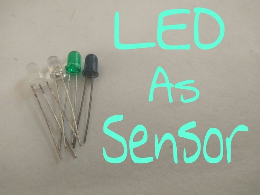
What you’ll need:


Hardware Configurations:
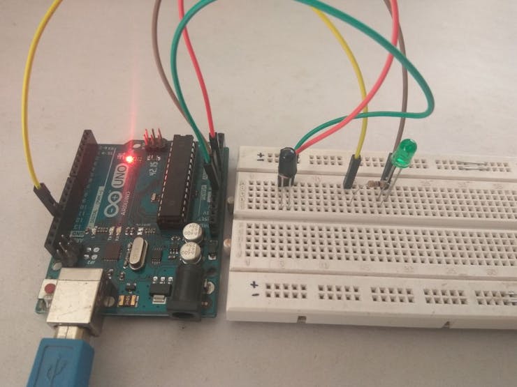
Step 1: Place the LED sensor in the breadboard
Step 2: Connect one pin to the A0 (analog pin) of Arduino, and connect another pin to the GND pin of Arduino.
Step 3: Place another LED on a breadboard and connect a 220-ohm resistor to its Anode.
Step 4: Connect a wire from the resistor to pin 13 on Arduino (digital pin). Connect the Cathode of the LED to the GND of Arduino.
Software configurations:
Step 1: Install Arduino IDE if you’ve yet to
Step 2: Copy the code below and upload it to Arduino
/* To read values from led as a sensor. Upload the code in arduino.
 * Connect the LED to pin A0 (analog pin) of arduino.
 * Connect second pin to GND.
 * Open serial monitor to see the values.
 *Code by Harsh Dethe.
*/

int sensor = A0;  // define analog pin A0. (input/sensor)

void setup()
{
  Serial.begin(9600); //sets serial communication between arduino and computer
  pinMode(sensor,INPUT); // sets analog pin A0 as input.
}

void loop()
{
  int value = analogRead(sensor); // sets variable "value" to store value of sensor.
  Serial.println(value); //prints values in serial monitor
  delay(500); //half a second delay
}
Step 3: Head to tools in Arduino IDE and open the serial monitor. Note the values in the dark and values after the light is applied. These values are used to trigger the switch.
Step 4: If in the dark value is 100-150, and in the light, it is 50-100, the LED on pin 13 can be turned on by editing the if statement as below:
if(value > 100 )
{
    digitalWrite(led,HIGH);
}
Now the LED will turn on when in the dark and if the greater than “>” is replaced with less than “<” then the LED will turn on in the light.
Still uncertain about how it works and need a video tutorial? Thanks to WolfxPac on Hackster.io, here’s the video tutorial!
Notification Lamp Project
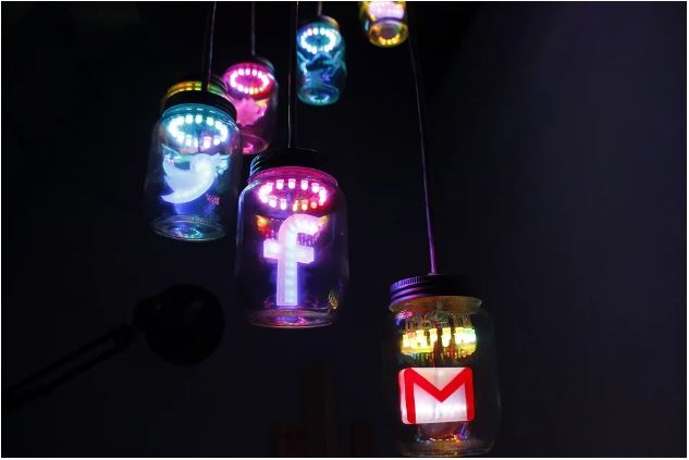
What you’ll need:
- Intel Edison Breakout Kit
- Arduino Base Shield V2
- Arduino Pro Mini
- Breadboard
- LM2596 Step-Down Power Module
- Mini PIR Motion Sensor
- PCB Sheet
- RGB LEDs
- 8-bit Shift Register
- Octal Bus Transceiver
- Electrolytic Decoupling Capacitors
- Printed Circuit
- Frames for Icons
- Glass Jars
Hardware Configuration:
Resources and Going Further
Breadboard Jumper Wires available at Seeed:
- Grove 4-pin Female Jumper to Grove 4-pin Conversion Cable
- 2-pin Dual-Female Jumper Wire – 300mm
- 4-pin Dual-Female Jumper Wire – 300mm
More on breadboard projects:
- Breadboard projects on hackster.io
- Arduino breadboard projects on fritzing
Getting started with breadboard on other microcontroller platforms:
Summary
That’s all for today on breadboards. I hope with today’s blog, you get a deeper understanding of how a breadboard works and how to use it with Arduino!
With breadboard able to house both simple and very complex electrical circuits, it’s not only a common but popular option for prototyping and testing out new parts!
- Grab a breadboard today and get started with your breadboard projects!