Getting Started With SAMD21 Arduino
Looking for a powerful microcontroller as an alternative to the Arduino? Why not consider the ATSAMD21 which can be programmed by the Arduino IDE?
What is SAMD21?
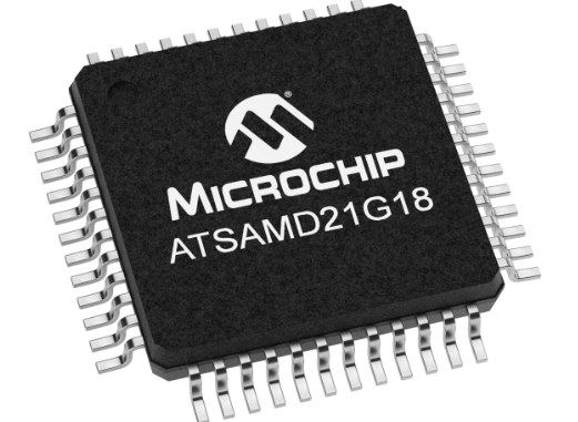
The Atmel’s ATSAMD21 is a low-power, high-performance Microchip’s ARM® Cortex®-M0+ based flash microcontroller. Here are its features:
- 256KB of flash and 32KB of SRAM
- 48MHz Operating Frequency
- Full Speed USB device and embedded host
- Support for up to 120 touch channels
- 1.62V to 3.63V power supply
- Six serial communication modules (SERCOM) configurable as UART/USART, SPI or I2C, three 16-bit timer/counters, 32-bit Real-Time Clock and calendar, 20 PWM channels, one 14-channel 12-bit ADC, one 10-bit DAC
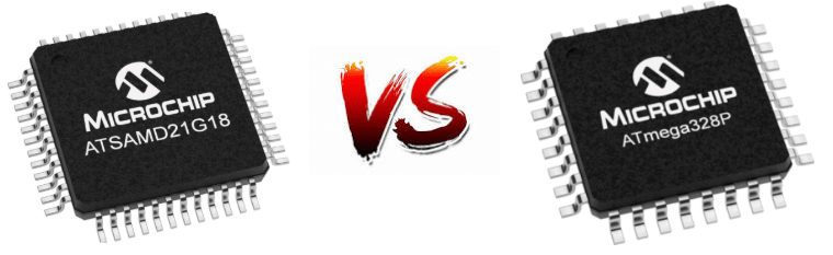
As you can see this is a very powerful microcontroller compared to the older 8-bit/16MHz Arduino microcontrollers. To just show you how powerful they are, we compared them side by side with the ATmega328P that is on your Arduino UNO:
| Features | ATSAMD21G18A | ATmega328p |
| Architecture | ARM® Cortex®-M0+ | AVR |
| Bus Size | 32 Bit | 8 Bit |
| CPU Speed | 48MHz | 20MHz |
| Flash | 256KB | 32KB |
| SRAM | 32KB | 2KB |
| EEPROM | 32KB | 1KB |
| Voltage Range | 1.62V to 3.63V | 1.8V to 5.5V |
| GPIO Count | 38 | 23 |
| ADC Channels | 14 | 8 |
| ADC Resolution | 12 Bit | 10 Bit |
| USB Controller |  |  |
| Digital-to-Analog Converter (DAC) | | |
| Peripheral Touch Controller | | |
| Direct Memory Access (DMA) | 12 Channels | |
From the above table, you can see that in almost every factor, the ATSAMD21 stands out. However, this doesn’t mean that the ATmega328p is that bad! The ATmega328p also features a few advantages like having a bigger community for troubleshooting, well documented, simpler to use and they are able to operate at 5V.
On the other hand, if you are looking for a better microcontroller, the SAMD21 will definitely act as a good alternative at around the same price!
Not convinced? Here are some more reasons why you should you use the SAMD21:
Why use the SAMD21?
Large Memory and Fast Operating Speed
Restricted by storage limits on your Arduino UNO? Or feel that other microcontrollers operating speed are just too slow? Well the SAMD21 will solve all of your issues.
The SAMD21 256KB of flash means you would not be limited to only 32KB of space where you have to fit all of your compiled sketch into. In addition, extra flash storage means you can store large, user-defined blocks of data as well into your microcontroller. Not to mention it features 32KB SRAM where you do not have to worry about dynamic memory stack overflows anymore.
Furthermore, with SAMD21 max CPU speed of 48MHz, operating speeds will not be a worry anymore.
Sensitive Voltage Measurements
The SAMD21 features 14 ADC input pins with a 12-bit resolution compared to 10-bit on the ATmega328p. The increased resolution means that every bit between 0 and 4095 represents 0.806mV when the processor is powered at 3.3V which equals a more sensitive voltage measurement.
Integrated USB Controller
The ATSMAD21 is equipped with an integrated USB controller which can be used as either a USB device or host.
As a USB device, it is able to emulate a keyboard, mouse or joystick,etc. It is able configure itself as a USB communication device class where you can connect it with a computer where you can talk to it as a serial port.
On the other hand, as a USB host, the ATSAMD21 can connect a mouse or keyboard or also save data to a USB flash drive.
RTC (Real time clock) onboard
Need precise time-keeping for your digital clock or PID loop? Even though the ATmega328 has an RTC on board, it is required for timekeeping. The SAMD21 also has an RTC that is powered separately by an on-board crystal while it still clocks the processor at 48MHz.
Configurable Serial Interfaces
This is one of the most unique features that make the SAMD so special. It is as has a set of 6 configurable serial interfaces that can be turned into either a UART, I2C master, I2C slave, SPI master or SPI slave.
Due to this feature, it provides you with a lot of flexibility as the ports can be multiplexed which gives you a choice of which task each pin is assigned.
Getting Started with SAMD21 Arduino
Firstly you will need a SAMD21 Board to get started. Here at Seeed, we have 3 cost-effective SAMD21 Arduino compatible boards which are:
Seeeduino Cortex-M0+
- The Seeeduino Cortex-M0+ features an Atmel SAMD21 MCU which is based on a 32-bit ARM® Cortex®-M0+ processor.
- With the help of this powerful core, SAMD21 is much more powerful than AVR and can achieve many functions and more complex calculations that cannot be implemented on AVR chips.
- The Seeeduino Cortex-M0+ has the same header pinout as the Seeeduino Lotus Cortex-M0+, including 14 digital I/O (10 PWM output) and 6 analog I/O. In the meantime, it provides 3 on-board Grove connector: two I2C and 1 UART. If you want more grove ports, you can use a Base Shield V2 to work with this board.
- On top of that, Seeeduino Cortex-M0+ is the first Seeeduino development board with a USB type C interface. USB Type C is the future trend: the plugs are reversible, higher data transfer rate, and more scalable functions.
- For the Seeeduino Cortex-M0+ pinout and hardware overview, you can check out our Wiki here!
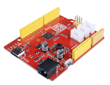
Seeeduino Lotus Cortex-M0+
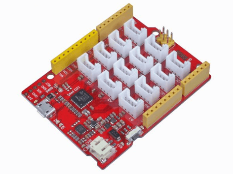
- Seeeduino Lotus Cortex-M0+ is a SAMD21 Microcontroller development board. The Atmel® | SMART™ SAM D21 is a series of low-power microcontrollers using the 32-bit ARM® Cortex®-M0+ processor with 256KB Flash and 32KB of SRAM. you can consider the Seeeduino Lotus Cortex-M0+ as a combination of Seeeduino and Base Shield.
- Seeeduino Lotus Cortex-M0+ has 14 digital input/outputs (10 of which support PWM) and 6 analog input/outputs, 3 Serial Communication Interface, a micro USB connector, a JST2.0 Li-Po connector, an ICSP header, 12 Grove connectors, a reset button.
- Seeeduino Lotus Cortex-M0+ is an upgraded version of Seeeduino Lotus V1.1, it replaces a more powerful chip, optimizes the circuit layout, and the power supply is more stable. Because this chip supports direct USB level output, there is no need to use a serial port to USB chip, like CP2102N. Therefore, one more hardware serial port is available to the user.
- For the Seeeduino Lotus Cortex-M0+ hardware overview and pinout, you can check out our wiki here!
Wio Lite MG126 – ATSAMD21 Cortex-M0 Blue Wireless Development Board
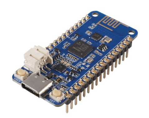
- Wio Lite MG126 is a cost-effective SAMD21 based development board with the on-board MG126 Bluetooth Module. SAM D21 is an ARM Cortex-M0+ based microcontroller and the MG126 is a 2.4GHz single-mode Bluetooth transceiver module.
- In addition, this board is also compatible with Arduino Zero and has the same compatible form factor with Adafruit Feather series.
- We break out the 3.3V I/O pins of SAM D21, SAM D21 chip has rich I / O resources, including 14 digital pins, 6 analog pins, 1 UART port, 1 I2C port, and 1 ICSP port.
- There is a JST2.0 Li-Po battery port, you can use 3.5V or 4.2V Li-Po battery to power this board.
- Now, let’s talk about the Bluetooth Core, the MG126. MG126 is a 2.4GHz BLE RF transceiver with software configurable registers, embedded packet handling engine.
- It can work with ultra-low power. The Bluetooth air data rate of MG126 is 1Mbps and MG126 can talks with Arduino core at the speed of 4Mbps via the SPI interface.
Step by Step Instructions for Seeeduino Boards
If you decide to use the Seeeduino Cortex-M0+ or the Seeeduino Lotus Cortex -M0+ this tutorial is for you! If not, scroll down for the tutorial on Wio Lite MG126!
Step 1: Prepare the materials required
You will need:
- Seeeduino Cortex-M0+ / Seeeduino Lotus Cortex-M0+
- Type C cable (For Seeduino Cortex M0+) / Micro USB Cable (Seeeduino Lotus Cortex M0+)
- Computer
Step 2: Download Arduino IDE
Before you start, you will require an Arduino Software called to program the board. After you are done downloading, launch the application.

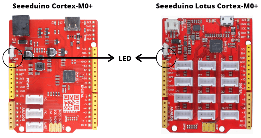
Step 3: Connect your Seeeduino
Connect your Seeeduino to your computer using the USB cable. The blue power LED (labelled PWR) should light up after it is successfully connected.
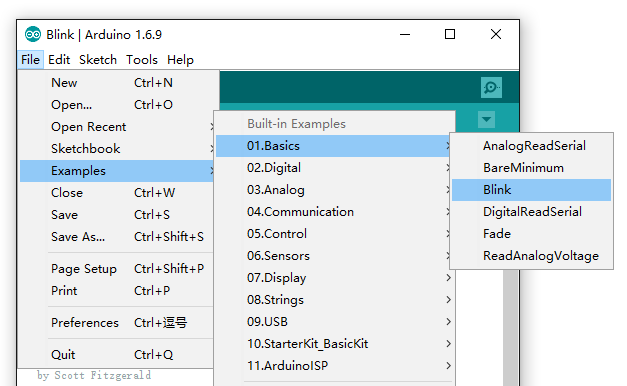
Step 4: Open the Blink Example on Arduino IDE
Open the LED blink example sketch on your Arduino IDE: File > Examples > 01. Basics > Blink
Step 5: Add your Seeed board
Please follow the Seeed Board Intallation Guide and search the keyword samd_zero / lotus M0 to add the Seeeduino Cortex-M0+ / Seeeduino Lotus Cortex-M0+ into your Arduino IDE.


Step 6: Select your board and port
You’ll need to select the entry in the Tools > Board menu that corresponds to your Arduino. Selecting the Seeeduino Cortex-M0+ or Seeeduino Lotus Cortex-M0+.

Select the serial device of the Arduino board from the Tools | Serial Port menu. This is likely to be COM3 or higher (COM1 and COM2 are usually reserved for hardware serial ports). To find out, you can disconnect your Arduino board and re-open the menu; the entry that disappears should be the Arduino board. Reconnect the board and select that serial port.

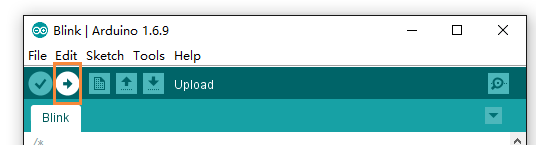
Step 7: Upload the program
Now, simply click the “Upload” button in the environment. Wait a few seconds and if the upload is successful, the message “Done uploading.” will appear in the status bar.
A few seconds after the upload finishes, you should see the pin 13 (L) LED on the board start to blink. If it does, congratulations! You’ve gotten Arduino up-and-running.
Step by Step Instructions for Wio Lite MG126
This is the step by step tutorial for the Wio Lite MG126 – ATSAMD21 Cortex-M0 Blue Wireless Development Board!
Step 1: Prepare the materials required
You will need:
- Wio Lite MG126
- Type C cable
- Computer
- Jumper
Step 2: Downloading Relevant materials
Before you start, please download the nRF Connect app from Google/Apple Store. nRF Connect is compatible with standard Bluetooth protocol functions, all examples are tested based on this app.
In addition, you will require an Arduino Software called to program the board. After you are done downloading, launch the application.
Step 3: Add the Wio Lite MG126 Board into Arduino IDE
Open your Arudino IDE, click on File > Preferences, and copy the following URL to Additional Boards Manager URLs.
https://raw.githubusercontent.com/Seeed-Studio/Seeed_Platform/master/package_seeeduino_boards_index.json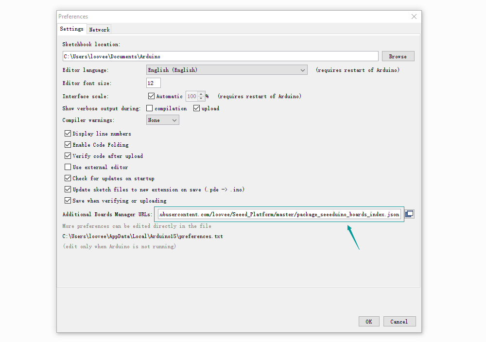
Click on Tools > Board > Board Manager. Search the board by name, just search the keyword Seeeduino_Wio_Lite_MG126 and install the corresponding board.

Step 4: Select your board and port
You’ll need to select the entry in the Tools > Board menu that corresponds to your Arduino and select Wio Lite MG126.

Select the serial device of the Arduino board from the Tools | Serial Port menu. This is likely to be COM3 or higher (COM1 and COM2 are usually reserved for hardware serial ports). To find out, you can disconnect your Arduino board and re-open the menu; the entry that disappears should be the Arduino board. Reconnect the board and select that serial port.
You may not find the MG126 examples in the File > Examples tab before you select the wio Lite MG126 board. When you select the board, the examples will appear here.
Step 5: Open the demo
Click on File > Examples > Examples for Seeeduino Wio Lite MG126 > wio_lite_ble >example >analog_output.

It is important to note that since the arduino IDE is temporarily incompatible with static libraries (our Bluetooth protocol stack is compiled into a static library), the following configuration needs to be changed when the example uses the Bluetooth library.
- Open the
platform.txtfile in the folder:
C:\Users\$(USER_NAME)\AppData\Local\Arduino15\packages\Seeeduino\hardware\Seeeduino_Wio_Lite_BLE\1.0.0\platform.txt- Go to line 75 and line 76.
##recipe.c.combine.pattern="{compiler.path}{compiler.c.elf.cmd}"  "-L{build.path}" {compiler.c.elf.flags} {compiler.c.elf.extra_flags} "-T{build.variant.path}/{build.ldscript}" "-Wl,-Map,{build.path}/{build.project_name}.map" --specs=nano.specs --specs=nosys.specs {compiler.ldflags} -o "{build.path}/{build.project_name}.elf" {object_files} -Wl,--start-group {compiler.arm.cmsis.ldflags} -lm "{build.path}/{archive_file}" -Wl,--end-group

recipe.c.combine.pattern="{compiler.path}{compiler.c.elf.cmd}" "-L{build.path}" {compiler.c.elf.flags} {compiler.c.elf.extra_flags} "-T{build.variant.path}/{build.ldscript}" "-Wl,-Map,{build.path}/{build.project_name}.map" --specs=nano.specs --specs=nosys.specs {compiler.ldflags} -o "{build.path}/{build.project_name}.elf" {object_files} {compiler.libraries.ldflags} -Wl,--start-group {compiler.arm.cmsis.ldflags} -lm "{build.path}/{archive_file}" -Wl,--end-group- If the sample program has a Bluetooth library called, you need to add
##in front of line 75 (ie, comment the line), at the same time, you need to delete##in front of line 76 (ie, uncomment). Conversely, if the Bluetooth library is not called, but the basic operation of the SAM D21 development board is used, the operation is reversed.
You can find 7 demos in this folder. The button/get_bat_vol demos do not use the bluetooth library, and the rest do.

| Demo Name | Function | Device Info |
|---|---|---|
| analog_output | The analog value on the development board is obtained via Bluetooth and displayed on the mobile app. | Wio_BLE_Analog |
| button | Press onboard user button and print in the serial monitor. | |
| echo_ble | Bluetooth echo server, that is, the mobile phone receives the data sent by the development board. | Wio_Lite_BLE |
| get_bat_vol | Get the external battery voltage | |
| rgb_led_matrix_control | Control the Grove – RGB LED Matrix to display | Wio_Led_matrix |
| serial_transparent_transmission | The serial port data is transparently transmitted, that is, the data sent by the mobile phone will be sent from the serial port of the development board, and the data sent to the serial port of the development board will be sent to the mobile phone. | Wio_Lite_Serial |
| temp_humidity | Get the information from Grove – I2C High Accuracy Temp&Humi Sensor (SHT35),and sent it to your phone. | Wio_BLE_T&H |
Step 6: Upload the program
Now, simply click the “Upload” button in the environment. Wait a few seconds and if the upload is successful, the message “Done uploading.” will appear in the status bar.
When it is finished the information Done Uploading will Pop up in the lower-left corner of Arduino IDE.
Step 7: Use the phone to connect MG126
Open the nRF Connect app, click on the SCANNER and search for the name of the DeviceInfo in the page. Different demos have different DeviceInfo, the and the corresponding DeviceInfo of analog_output is Wio_BLE_Analog.
So, please choose the Wio_BLE_Analog in the bluetooth device list. Tap CONNECT, then click Automation IO > Analog, and the value of A0 pin will be displayed.

Due to the caching function of Bluetooth, every time you modify the feature value of Bluetooth (that is, download the example using different Bluetooth functions), you need to clear the cache of the app once, also you need to restart the phone.
And you are done! Below are the function interface:
WiFi function interface
- Bluetooth package class
MG126_Ble - Initialize the Bluetooth protocol stack and turn on Bluetooth
MG126_Ble .ble_init();- Reporting messages via Bluetooth
sconn_notifydata();These are just a few common interfaces! If you want to view other interfaces, you can view the examples.
Summary
With the SAMD21, you can do much more with Arduino and ARMs working together! What do you think about the SAMD21? Let us know in the comments down below!