Micro:bit Project – Getting Started with Bitmaker
Before you proceed, if you have not yet started with your micro:bit you can check out our other blog on Getting Started with micro:bit: Makecode, Accessories, Projects.
In addition, you can also check out our other blog on 25 micro:bit projects for beginners that you must try now for more project ideas!
Getting started with Bitmaker
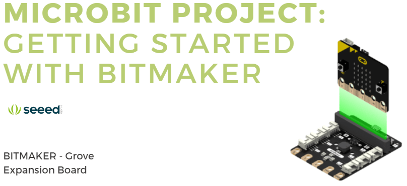
Feel that onboard I/O rings and crocodile clips are not handy and safe enough to connect peripherals? With this project, you do not have to worry about that anymore with the help of the Bitmaker, a Grove Expansion Board!
What is the Bitmaker?

BitMaker is a Grove expansion board specially designed for the BBC micro:bit. Users can insert the micro:bit into the micro:bit slot on the expansion board, and use it to control the Grove module connected to the Grove ports.

In addition to the large range of Grove modules available, the BitMaker board itself includes programmable RGB LEDs and a buzzer, both components which will come in handy in many projects! This not only eliminates the need to procure extra components, but enables novice users to experience hardware features without connecting extra components.
Wait a minute, what is Grove?

Grove is Seeed’s very own modular, standardized connector prototyping system. Grove takes a building block approach to assemble electronics. Compared to the jumper or solder based system, it is easier to connect, experiment and build and simplifies the learning system.
Combine the micro:bit and the Grove System, you get a system perfect for beginners and also children to learn electronics and programming!
For example, some functions you can add to your Micro:bit easily using the Bitmaker are gesture control, ultrasonic transducer and more RGB LEDs!
What are the features of the Bitmaker?

- Plug and Play
- 4 Programmable RGB LEDs and a buzzer
- 6 Grove Connection Ports
- Fully compatible with Microsoft Makecode Editor
- Accessible micro:bit touch pins and includes power on/off switch and indication light.
Without further ado, let us show you guys how to easily get started with the Bitmaker and Micro:bit!
Get Started with MakeCode to Program the micro:bit and Bitmaker
Similar to the micro:bit, the Bitmaker can be easily programmed in Makecode. To do this, you just have to add an extension to your Makecode!
What is Makecode?
Microsoft Makecode is a framework for creating interactive and engaging programming experiences for those new to the world of programming like children and beginners. With Makecode, users can easily program the micro:bit.
Makecode uses blocks programming model to let users learn coding concepts in a simplified manner. Once you are familiarised with the coding elements and structure, you can progress to create more complex programs. Not only is Makecode easy to operate, they are also easily accessible via an Internet Browser.
Getting Started
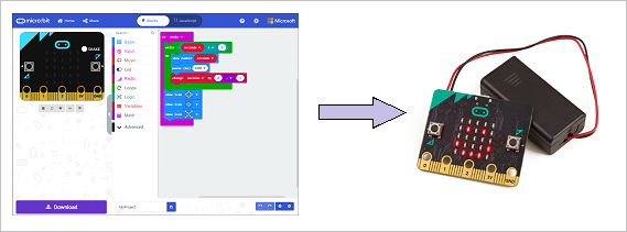
Step 1: Open up Make Code internet browser
- Go to Makecode for micro:bit here!

Step 2: Connect micro:bit to PC and start new project
- Connect micro:bit to a PC with USB cable.
- If successfully connected, the power indicator LED on the back of micro:bit will light up and you should see it appear on your “My PC” page.
- Next, create a new project on Makecode editor which would take you to the workspace as shown below:

Step 3: Add Bitmaker Extensions
- Click on the gear icon (Settings option) on the blue bar in MakeCode and select “Extension” from the drop-down list.

- Enter this following URL into the search box to add Bitmaker Extension: https://github.com/TinkerGen/pxt-BitMaker

- Return to your workspace where you should notice that the BitMaker extension is already added.
- Take note that after you have downloaded the program to micro:bit, make sure the Bitmaker is connected via a micro USB cable.
Step 4: Using the Buzzer
- As the buzzer on the BitMaker board is connected to the default pin (P0) it makes it very easy to use in MakeCode. All you need to do is open the music-tab and drag-and-drop the code block into the main window

- For example, this command would play a melody once the micro:bit is turned on or reset.

Step 5: Using the Neopixel RGB LED
- You can also control the Bitmaker onboard RGB LED using the Neopixel block via P13. We will show you an example where we use it turn its colour to blue one by one.
- To do this, firstly create a new project. Go to extensions and select “neopixel” from pop-up page as shown below:

- Add example program as shown below

- You should see your LEDs flashing one by one in blue colour:
That is all on how to get started with Bitmaker and use its onboard functions using Makecode!
Now, we will show you how to use the Grove connectors with our Grove modules with the Bitmaker!
Using Grove with Bitmaker


Firstly, you would have to add the Grove Extension with the following URL: https://github.com/TinkerGen/pxt-Grove
You can refer to step 3 on how to add extension previously. Just replace the URL with the above URL!
So to use Grove with Bitmaker, you would have to understand the Bitmaker blocks and how to use them. There are a total of 6 Blocks.
Analog Read Pin

This block is able to read the analog inputs at the specified Grove (P0, P1 or P2 on Bitmaker) as a value between 0 and 1023.
Example 1
This program reads pin [P1] and shows the number on the LED screen:

For this program, if you intend to use [P0], please turn off your buzzer or you might hear noises using this command:

Example 2
This program reads pin [P1] and map the value to 0 to 9 which will then show the result on the LED screen. The result will be a number between 0 and 9.

Analog Write Pin

This block will set the Grove port value as analog. Value must be between 0 and 1023.
Example
This program writes 1023 and 0 to pin [P1] every 1 second. If you connect a LED to [P1], you will see that the LED will be turned ON and OFF every 1 second.

Analog Set Pin

This block allows you to configure the period of Pulse Width Modulation (PWM) on the specified analog pin to a given value in microseconds. Before you use this function, you should set the specified pin as analog output using an analog write pin.
Example
This program first sets [P0] to analog with analog write pin, and then sets the PWM period to [P0] 20,000 microseconds (50Hz).

Digital Read Pin
Consists of 2 Blocks:

Allow you to read the specified pin or Grove port as either 0 or 1

Allow you to read the state of a pin or Grove port as either high or low.
Example:
The following two examples keep reading the digital input at [P1] in two different ways. If you connect a button to [P1], you can check if the button is pressed and use the button to control things like an LED or a motor.


Digital Write Pin

This block allow you to set a pin or Grove port to high or low.
Example
This following example shows you how to use button A and button B on micro:bit to control the state of pin [P1]. If you connect a LED to [P1], you can click button A to turn on the LED and click button B to turn it off.

I2C

This block is for advanced users! They are used to control I2C devices. Up for the challenge? You can find the full tutorial here:
Summary
That’s all on How to get started with Bitmaker with the micro:bit! Now that you have learn all the basics, you are ready to make micro:bit projects with the Bitmaker!
You can get a free STEM course set where you will learn how to make 12 projects. All you need to do is sign up. If you are interested, check out the course here!