LSM303 Accelerometer: Arduino, Raspberry Pi Guide to get started

Looking for a 3-axis accelerometer that’s easily pairable with your Arduino and has a magnetometer (compass) onboard? The LSM303 based Grove 6-Axis Accelerometer&Compass v2 does just that!
In today’s’ blog, I’ll be introducing the LSM303 Accelerometer and showing you how to connect the LSM303 to an Arduino and Raspberry Pi. All to help you get started!
Note: This blog includes the LSM303 datasheet for your reference as well!
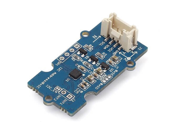
LSM303 Based Module: Grove – 6 Axis Accelerometer&Compass v2.0

Based on the LSM303D, this accelerometer is packed with 3 magnetic field channels and 3 acceleration channels. This enables electromagnetic field and gravitational force readings all in a small package!
Not only that, the Grove – 6-Axis Accelerometer&Compass doesn’t lose out to other popular mems accelerometers you’ve heard and known today as well!
- It matches the ±16g accelerometer output that adxl345 offers
- Its 16-bit data output makes it easily parable with a microcontroller
- Onboard 3D magnetometer that’s lacking on the adxl345 allows for a wider range of applications
Here are its features:
- Input Voltage: 5V
- SPI/I2C Interfaces (Selectable)
- 2 Independent programmable Interrupt
- Wide Full-Scale Range
- ±2/±4/±8/±12 gauss magnetic full scale
- ±2/±4/±6/±8/±16g acceleration full scale
- 6D orientation detection
- Power-down Mode / Low-power Mode
Key applications include:
- Pedometers
- Free-fall detection
- Display orientation
- Gaming and virtual reality input devices
- Vibration monitoring and compensation
- Position detection
Hardware overview with Pinout:
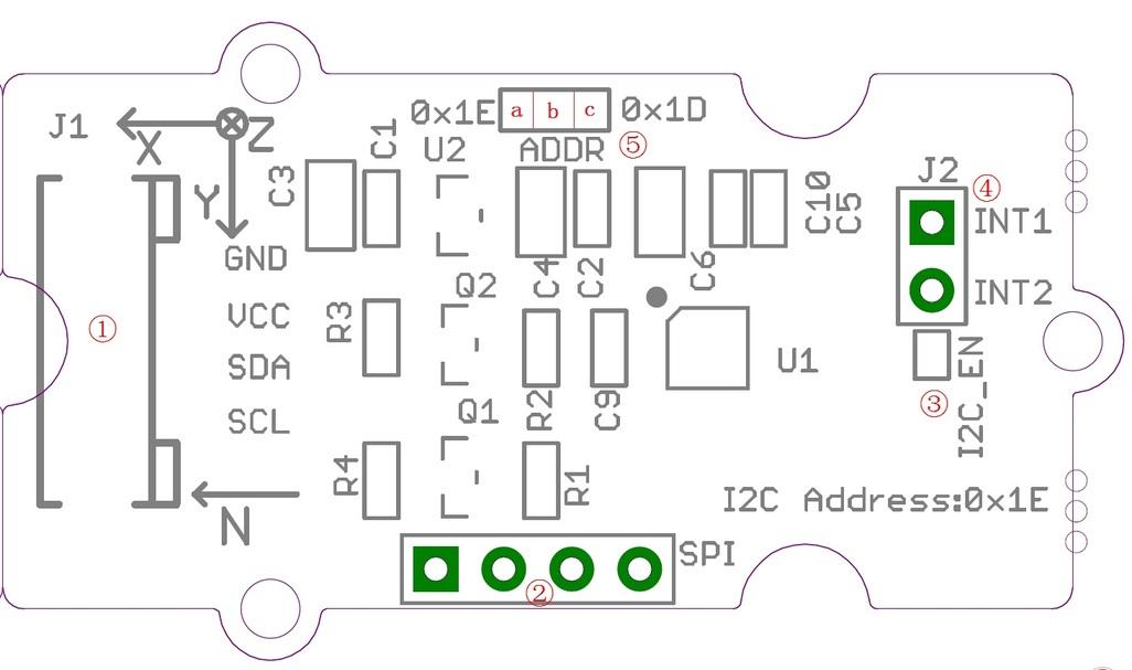
- Pin 1: Grove interface, connect to I2C
- Pin 2: SPI Interface
- Pin 3: I2C or SPI select pad (default is I2C).
- Disconnect this pad if you want to use SPI
- Pin 4: Interrupt digital output
- Pin 5: Address select pad
- By default, connected b and a address is 0x1E, if connect b and c address is 0x1D
- If you want to use SPI, disconnect this pad to either side
Why you should pick this LSM303 module instead of other breakout boards in the market?
You can find other LSM303 breakout boards, sensors, modules, etc. available, but what makes the Grove – 6-Axis Accelerometer&Compass V2.0 the one to go with? Here’s why!
Ease of pairing LSM303 with Arduino through Seeed’s very own Grove system
Grove system is Seeed very own initiative, mainly aimed at helping users like yourself to easily use different modules, through our plug and play system!
This means no more using messy and complicated jumper wires, soldering, breadboard, or debugging electronic circuits!
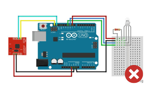
Like how simple and less messy it is compared to other VL53L0X modules?
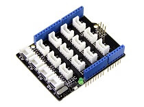
All you need is a Grove Base Shield alongside your Arduino and you’re good to go! Switch to using grove today!
LSM303 Arduino and Raspberry Pi Guide
We’ve provided both Arduino and Raspberry Pi library to help you get started.
LSM303 Arduino Guide
To get started, you’ll first need the following:
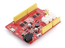
*Seeeduino is Seeed’s very own Arduino, built with benefits over the regular Arduino boards.
Hardware configurations:
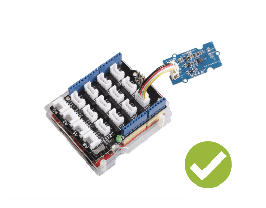
- Step 1: Connect the Grove – 6-Axis Accelerometer&Compass V2.0 to port I2C of Grove-Base Shield
- Step 2: Plug Grove – Base Shield to Seeeduino
- Step 3: Connect Seeeduino to PC via a USB cable
It should look like this after pairing things up:

Software configurations:
- Step 1: Download the library from Github
- Step 2: Refer to How to install library to install library for Arduino
- Step 3: Create a new Arduino sketch and paste the codes below to it or open the code directly by the path: File -> Example ->Accelerometer_Compass->Accelerometer_Compass
- Step 4: Upload the following code. If you do not know how to upload the code, please check how to upload code
/* LSM303DLM Example Code base on LSM303DLH example code by Jim Lindblom SparkFun Electronics

   date: 9/6/11
   license: Creative commons share-alike v3.0

   Modified by:Frankie.Chu
   Modified by:Jacky.Zhang 2014-12-11: Ported to 6-Axis Accelerometer&Compass of Seeed Studio
   Modified by:Jacky.Zhang 2015-1-6: added SPI driver

   Summary:
   Show how to calculate level and tilt-compensated heading using
   the snazzy LSM303DLH 3-axis magnetometer/3-axis accelerometer.

   Firmware:
   You can set the accelerometer's full-scale range by setting
   the SCALE constant to either 2, 4, or 8. This value is used
   in the initLSM303() function. For the most part, all other
   registers in the LSM303 will be at their default value.

   Use the write() and read() functions to write
   to and read from the LSM303's internal registers.

   Use getLSM303_accel() and getLSM303_mag() to get the acceleration
   and magneto values from the LSM303. You'll need to pass each of
   those functions an array, where the data will be stored upon
   return from the void.

   getHeading() calculates a heading assuming the sensor is level.
   A float between 0 and 360 is returned. You need to pass it a
   array with magneto values.

   getTiltHeading() calculates a tilt-compensated heading.
   A float between 0 and 360 degrees is returned. You need
   to pass this function both a magneto and acceleration array.

   Headings are calculated as specified in AN3192:
   http://www.sparkfun.com/datasheets/Sensors/Magneto/Tilt%20Compensated%20Compass.pdf
*/

/*
hardware & software comment
I2C mode:
1, solder the jumper "I2C EN" and the jumper of ADDR to 0x1E
2, use Lsm303d.initI2C() function to initialize the Grove by I2C
SPI mode:
1, break the jumper "I2C_EN" and the jumper ADDR to any side
2, define a pin as chip select for SPI protocol.
3, use Lsm303d.initSPI(SPI_CS) function to initialize the Grove by SPI
SPI.h sets these for us in arduino
const int SDI = 11;
const int SDO = 12;
const int SCL = 13;
*/

#include <LSM303D.h>
#include <Wire.h>
#include <SPI.h>

/* Global variables */
int accel[3];  // we'll store the raw acceleration values here
int mag[3];  // raw magnetometer values stored here
float realAccel[3];  // calculated acceleration values here
float heading, titleHeading;

#define SPI_CS 10

void setup()
{
    char rtn = 0;
    Serial.begin(9600);  // Serial is used for debugging
    Serial.println("\r\npower on");
    rtn = Lsm303d.initI2C();
    //rtn = Lsm303d.initSPI(SPI_CS);
    if(rtn != 0)  // Initialize the LSM303, using a SCALE full-scale range
    {
        Serial.println("\r\nLSM303D is not found");
        while(1);
    }
    else
    {
        Serial.println("\r\nLSM303D is found");
    }
}

void loop()
{
    Serial.println("\r\n**************");
    //getLSM303_accel(accel);  // get the acceleration values and store them in the accel array
    Lsm303d.getAccel(accel);
    while(!Lsm303d.isMagReady());// wait for the magnetometer readings to be ready
    Lsm303d.getMag(mag);  // get the magnetometer values, store them in mag

    for (int i=0; i<3; i++)
    {
        realAccel[i] = accel[i] / pow(2, 15) * ACCELE_SCALE;  // calculate real acceleration values, in units of g
    }
    heading = Lsm303d.getHeading(mag);
    titleHeading = Lsm303d.getTiltHeading(mag, realAccel);

    printValues();

    delay(200);  // delay for serial readability
}

void printValues()
{
    Serial.println("Acceleration of X,Y,Z is");
    for (int i=0; i<3; i++)
    {
        Serial.print(realAccel[i]);
        Serial.println("g");
    }
    //print both the level, and tilt-compensated headings below to compare
    Serial.println("The clockwise angle between the magnetic north and x-axis: ");
    Serial.print(heading, 3); // this only works if the sensor is level
    Serial.println(" degrees");
    Serial.print("The clockwise angle between the magnetic north and the projection");
    Serial.println(" of the positive x-axis in the horizontal plane: ");
    Serial.print(titleHeading, 3);  // see how awesome tilt compensation is?!
    Serial.println(" degrees");
}- Step 5: Open the serial monitor, you’ll see the output result of Color Sensor as shown below:
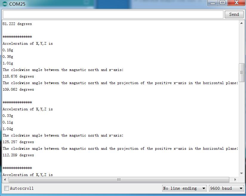
- Step 6: You can see the acceleration values and clockwise angle between the magnetic north and x-axis
The X/Y/Z shows the 3 axis acceleration, and then the angle between the magnetic north and x-axis calculated.
And also the angle between the magnetic north and the projection of positive x-axis calculated.
LSM303 Raspberry Pi Guide
The following tutorial uses the Raspberry Pi 3 Model B, though other models such as Pi B/B+/A+/2/3 fits as well.
What you’ll need to get started:
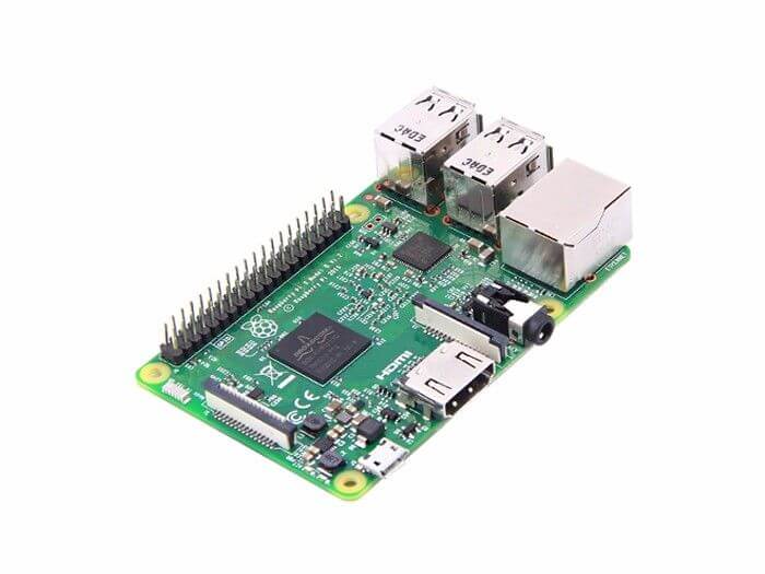
Raspberry PI 3 Model B 
GrovePi_Plus 
Grove – 6 Axis Accelerometer and Compass V2.0
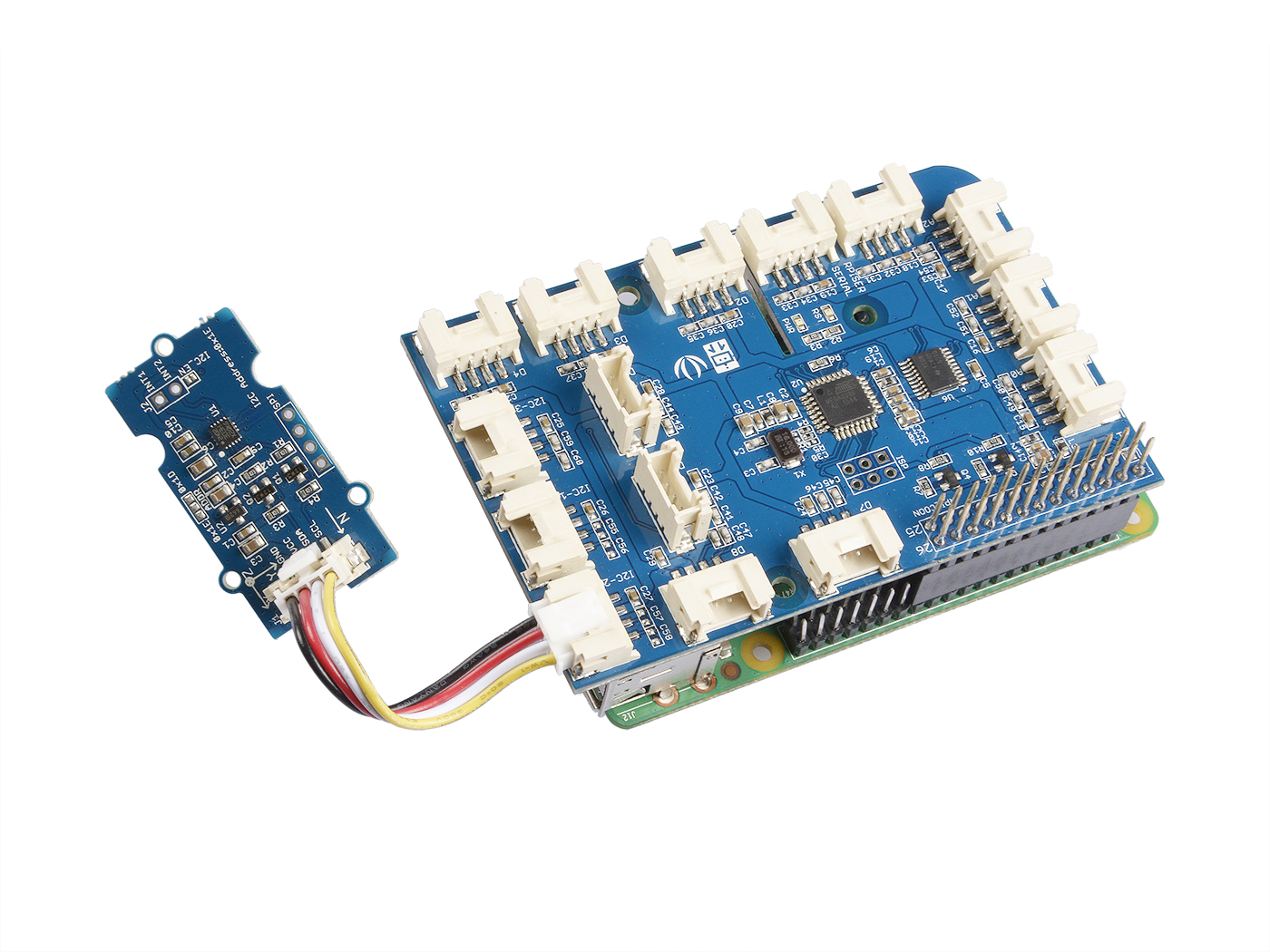
Hardware configurations:
- Step 1: Plug the GrovePi_Plus into Raspberry
- Step 2: Connect Grove -6-Axis Accelerometer and Compass V2.0 to I2C port of GrovePi_Plus
- Step 3: Connect the Raspberry to PC through USB cable
It should look something like this after pairing things up:
Software configurations
- Step 1: Follow Setting Software to configure the development environment
- Step 2: Git clone the Github repository
cd ~
git clone https://github.com/DexterInd/GrovePi.git- Step 3: Execute below commands to use this sensor
cd ~/GrovePi/Software/Python/grove_6axis_acc_compass
python grove_6axis_accel_compass_example.py
Here is the python code of example:
#!/usr/bin/env python
#
# GrovePi example for using the Grove - 6-Axis Accelerometer&Compass v2.0(http://www.seeedstudio.com/depot/Grove-6Axis-AccelerometerCompass-v20-p-2476.html)
#
# The GrovePi connects the Raspberry Pi and Grove sensors.  You can learn more about GrovePi here:  http://www.dexterindustries.com/GrovePi
#
# Have a question about this library?  Ask on the forums here:  http://forum.dexterindustries.com/c/grovepi
#
'''
## License
The MIT License (MIT)
GrovePi for the Raspberry Pi: an open source platform for connecting Grove Sensors to the Raspberry Pi.
Copyright (C) 2017  Dexter Industries
Permission is hereby granted, free of charge, to any person obtaining a copy
of this software and associated documentation files (the "Software"), to deal
in the Software without restriction, including without limitation the rights
to use, copy, modify, merge, publish, distribute, sublicense, and/or sell
copies of the Software, and to permit persons to whom the Software is
furnished to do so, subject to the following conditions:
The above copyright notice and this permission notice shall be included in
all copies or substantial portions of the Software.
THE SOFTWARE IS PROVIDED "AS IS", WITHOUT WARRANTY OF ANY KIND, EXPRESS OR
IMPLIED, INCLUDING BUT NOT LIMITED TO THE WARRANTIES OF MERCHANTABILITY,
FITNESS FOR A PARTICULAR PURPOSE AND NONINFRINGEMENT. IN NO EVENT SHALL THE
AUTHORS OR COPYRIGHT HOLDERS BE LIABLE FOR ANY CLAIM, DAMAGES OR OTHER
LIABILITY, WHETHER IN AN ACTION OF CONTRACT, TORT OR OTHERWISE, ARISING FROM,
OUT OF OR IN CONNECTION WITH THE SOFTWARE OR THE USE OR OTHER DEALINGS IN
THE SOFTWARE.
'''
import lsm303d

try:
    acc_mag=lsm303d.lsm303d()

    while True:

        # Get accelerometer values
        acc=acc_mag.getRealAccel()

        # Wait for compass to get ready
        while True:
            if acc_mag.isMagReady():
                break

        # Read the heading
        heading= acc_mag.getHeading()

        print("Acceleration of X,Y,Z is %.3fg, %.3fg, %.3fg" %(acc[0],acc[1],acc[2]))
        print("Heading %.3f degrees\n" %(heading))

except IOError:
    print("Unable to read from accelerometer, check the sensor and try again")
Here is the result:

Resources and Going Further
- [Library] 6-Axis Accelerometer&Compass v2.0 Library for Arduino
- [Library] 6-Axis Accelerometer&Compass v2.0 Library for raspberry pi
- [Datasheet] LSM303D datasheet
- [Eagle] 6-Axis Accelerometer&Compass v2.0 eagle file
- [Projects] 6-Axis Accelerometer&Compass v2.0 Project
- More on ADXL345 and memes accelerometer
Summary
Overall, with the LSM303 integrating a 3D compass sensor alongside the standard 3-axis accelerometer, it truly opens up a wider range of possibilities that’s applicable in day-to-day applications. With it, you can now easily orient your motion-sensing projects!
Consider the Grove – 6 Axis Accelerometer&Compass v2.0 (LSM303D), a module based on the LSM303 that’s easier to integrate with your Arduino and Raspberry Pi!
If you’re looking to find out more about mems accelerometer, particularly the ADXL series, you can check out this article!