Getting started with MPU-9250, Arduino Guide
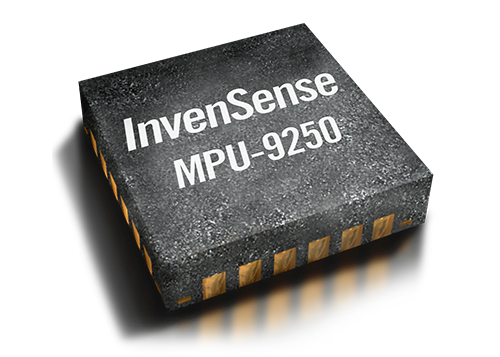
The MPU-9250 is a 9-axis MEMS sensor from InvenSense®. It’s Arduino compatible, making motion-tracking measurements simple. Compatibility aside, it’s a high performing device with low power consumption and a significantly smaller form factor as compared to its previous successor MPU-9150.
In today’s blog, I’ll be helping you get started with the MPU-9250, alongside how to hook it up with an Arduino.
MPU-9250 Introduction
Let’s get this blog started by firstly diving deeper into the MPU-9250 and giving you a better understanding of what this 9-axis MotionTracking Device is capable of.
How is the MPU-9250 9-axis?
Compared to other mems sensors; Accelerometer, Gyroscope, magnetometer, that are individually sold, the MPU-9250 combines it all. Integrating two dies into a single QFN package, it packs a 3-Axis Gyroscope and accelerometer on a die and the AK8963 3-Axis magnetometer on the other.
MPU-9250 Features
To better understand the features of each individual sensor, I’ve collated it in a table below:
| MPU-9250 | ||
|---|---|---|
| Gyroscope Features | Accelerometer Features | Magnetometer |
| Digital-output X-, Y-, and Z-Axis angular rate sensors (gyroscopes) with User-programmable full-scale range of ±250, ±500, ±1000, and ±2000°/sec and integrated 16-bit ADCs Digitally-programmable low-pass filter Gyroscope operating current: 3.2mA Sleep mode current: 8µA Factory calibrated sensitivity scale factor Self-test |
Digital-output triple-axis accelerometer with a programmable full scale range ±2g, ±4g, ±8g and ±16g and integrated 16-bit ADCs Accelerometer normal operating current: 450µA Low power accelerometer mode current: 8.4µA at 0.98Hz, 19.8µA at 31.25Hz Sleep mode current: 8µA User-programmable interrupts Wake-on-motion interrupt for low power operation of applications processor Self test |
3-axis silicon monolithic hall-effect magnetic sensor with magnetic concentrator Wide dynamic measurement range and high resolution with lower current consumption Magnetometer normal operating current: 280µA at 8Hz repetition rate Output data resolution of 14 bit (0.6µT/LSB) Full-scale measurement range is ±4800µT Self-test function with an internal magnetic source to confirm magnetic sensor operation on end products |
Apart from the above features coming from the MEMS gyroscope, accelerometer, and magnetometer, the MPU-9250 consists of other additional features!
Additional Features include:
- Smallest and thinnest QFN package for portable devices: 3x3x1mm
- Auxiliary master I2C bus for reading data from external sensors
- Minimal cross-axis sensitivity between the accelerometer, gyroscope and magnetometer axes
- 512 byte FIFO buffer enables the applications processor to read the data in bursts
- Digital-output temperature sensor
- 10,000 g shock tolerant
- 400kHz Fast Mode I2C for communicating with all registers
- Serial interfaces:
- 1MHz for communicating with all registers
- 200MHz for reading sensor and interrupt registers
The MPU-9250 can be found in a wide array of applications as well, including:
- Smartphones
- Tablets
- 3D remote controls for Internet-connected TVs and set-top boxes
- Motion-based game controllers and 3D mice
- Motion-based portable gaming
- Wearable Sensors
MPU-9250 vs MPU-9150: The Improvements
Before moving on to the integrated module, let’s take a look at what’s better on the MPU-9250 as compared to its previous successor!
Smaller and consume less power
As compared to the MPU-9150, the MPU-9250 has lowered its power consumption yet decreased form factor by 44%!
MPU-9250 has Better Gyro and Compass performance
The MPU-9250 contains:
- MPU-6500 and AK8963 magnetometer
The MPU-9150 contains:
- MPU-6050 and AK8975 magnetometer
What do the differences mean?
- MPU-6500 offers higher power, lower noise, and larger package as compared to the MPU-6050
- AK8963 magnetometer has a better full-scale range than the AK8975
Overall, you would expect an incremental increase in performance as it’s the latest 9-axis device from Invensense.
Getting started with MPU-9250
Grove – IMU 9DOF v2.0

In order to get started with the MPU-9250, you’ll first need a module that’s based on it. There are a number of breakout boards, modules, etc. on the market but today, I’ll be recommending the Grove – IMU 9DOF v2.0
First, a look at its features:
Since it’s an MPU-9250 integrated module, you’ll see similarities:
- I2C/SPI interface
- Auxiliary I2C
- Low Power Consumption
- 400kHz Fast Mode I2C for communicating with all registers
- Digital-output 3-Axis angular rate sensors (Gyroscopes) with a user-programmable full-scale range of
- ±250, ±500, ±1000, and ±2000°/sec
- Digital-output 3-Axis accelerometer with a programmable full-scale range of ±2g, ±4g, ±8g, and ±16g
- Digital-output 3-Axis accelerometer with a full-scale measurement range being ±4800μT
- I2C Address: 0x68
Why pick this MPU-9250 module rather than others?
Ease of pairing MPU-9250 with Arduino through Seeed’s very own Grove system
Grove system is Seeed very own initiative, mainly aimed at helping users like yourself to easily use different modules, through our plug and play system!
This means no more using messy and complicated jumper wires, soldering, breadboard, or debugging electronic circuits!

Like how simple and less messy it is compared to other MPU-9250 modules?
All you need is a Grove Base Shield alongside your Arduino and you’re good to go! Switch to using grove today!
MPU-9250 (Grove – IMU 9DOF v2.0) Arduino Guide
Now to answer the question you’ve been waiting for; How to pair the MPU-9250 with an Arduino? Here’s the guide to help you get started!
Note: This module is compatible with other microcontrollers but users have to write their own software library as it’s not possible to provide software library/demo code for all platforms
What you’ll need:


*Seeeduino is Seeed’s very own Arduino, built with benefits over the regular Arduino boards.
If you already own one of the Arduino models below, it’ll work with the Grove Base Shield as well:
- Arduino Uno
- Arduino Mega
- Arduino Leonardo
- Arduino 101
- Arduino Due
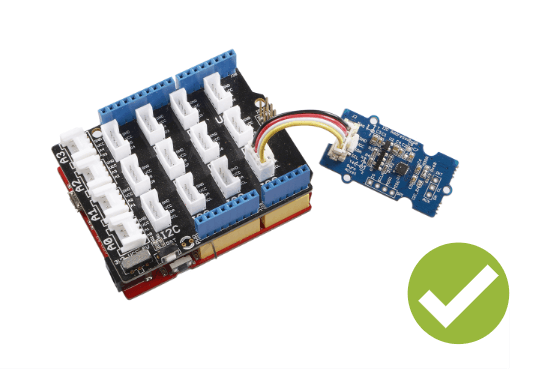
Hardware configurations:
- Step 1: Connect Grove-IMU_9DOF_v2.0 to port I2C of Grove Base Shield
- Step 2: Plug Grove Base Shield into Seeeduino
- Step 3: Connect Seeeduino to PC via a USB cable
It should now look something like this:

Software configurations:
- Step 1: Download the library from Github
- Step 2: Refer How to install library, and install library for Arduino
- Step 3: Create a new Arduino sketch and paste the codes below to it or open the code directly by the path: File -> Example ->IMU_9DOF_Demo_Compass_Calibrated->IMU_9DOF_Demo_Compass_Calibrated.
Here is the main part of the code:
void setup() {
  // join I2C bus (I2Cdev library doesn't do this automatically)
  Wire.begin();

  // initialize serial communication
  // (38400 chosen because it works as well at 8MHz as it does at 16MHz, but
  // it's really up to you depending on your project)
  Serial.begin(38400);

  // initialize device
  Serial.println("Initializing I2C devices...");
  accelgyro.initialize();

  // verify connection
    Serial.println("Testing device connections...");
    Serial.println(accelgyro.testConnection() ? "MPU9250 connection successful" : "MPU9250 connection failed");
    delay(1000);
    Serial.println("     ");

 //Mxyz_init_calibrated ();
}

void loop()
{
    getAccel_Data();
    getGyro_Data();
    getCompassDate_calibrated(); // compass data has been calibrated here
    getHeading();               //before we use this function we should run 'getCompassDate_calibrated()' frist, so that we can get calibrated data ,then we can get correct angle .
    getTiltHeading();

    Serial.println("calibration parameter: ");
    Serial.print(mx_centre);
    Serial.print("         ");
    Serial.print(my_centre);
    Serial.print("         ");
    Serial.println(mz_centre);
    Serial.println("     ");


    Serial.println("Acceleration(g) of X,Y,Z:");
    Serial.print(Axyz[0]);
    Serial.print(",");
    Serial.print(Axyz[1]);
    Serial.print(",");
    Serial.println(Axyz[2]);
    Serial.println("Gyro(degress/s) of X,Y,Z:");
    Serial.print(Gxyz[0]);
    Serial.print(",");
    Serial.print(Gxyz[1]);
    Serial.print(",");
    Serial.println(Gxyz[2]);
    Serial.println("Compass Value of X,Y,Z:");
    Serial.print(Mxyz[0]);
    Serial.print(",");
    Serial.print(Mxyz[1]);
    Serial.print(",");
    Serial.println(Mxyz[2]);
    Serial.println("The clockwise angle between the magnetic north and X-Axis:");
    Serial.print(heading);
    Serial.println(" ");
    Serial.println("The clockwise angle between the magnetic north and the projection of the positive X-Axis in the horizontal plane:");
    Serial.println(tiltheading);
    Serial.println("   ");
    Serial.println("   ");
    Serial.println("   ");
    delay(300);
}- Step 4: Upload the code and after that, you can see:
In the static state, the z-Axis output value is about 0.98g, so you can refer to above to see if your sensor can work normally.
Resources and Going Further
- [Eagle&PDF] Grove – IMU 9DOF v2.0 Eagle File
- [Library] Grove – IMU 9DOF v2.0 library
- [PDF] MPU-9250 datashet
- [PDF] MPU-9250 Register Map
Summary
Overall, MPU-9250 is an excellent choice for your motion-sensing needs. With Invensense support really good at staying in communication while they are looking over issues, you wouldn’t have to worry when troubleshooting occurs.
However, you’ll need a module that’s based on that motion processing unit for any pairings with a microcontroller.
I highly recommend the Grove – IMU 9DOF v2.0 simply with its ease of pairing when compared to other MPU-9250 breakout boards!