SPI – Introduction to Serial Peripheral Interface
Whether you are a beginner or an experienced engineer, you will definitely come across SPI one day. SPI is one of the most popular communication peripheral used by microcontrollers (eg. Arduino, Raspberry Pi) to send data to one or more peripheral devices like SD cards and sensors quickly over short distances.
Through this guide, we will cover the following content. It may look pretty long, but you can skip to the section you’re interested in:
- What is SPI
- SPI Interface
- SPI Data Transmission
- SPI Slave Selection
- Regular Independent Slave Configuration
- Daisy Chain Configuration
- Clock Polarity and Clock Phase
- Programming for SPI
- Arduino SPI
- Raspberry Pi SPI
- Advantages and Disadvantages of using SPI Protocol
- Tips and Tricks when using SPI
- Examples of SPI in Microcontrollers
What is SPI?
SPI is also known as Serial Peripheral Interface, it is a synchronous serial data protocol that acts as an interface bus which operates at full-duplex where data can be sent and received simultaneously which was developed by Motorola.
SPI Operate at faster data transmission rates = 8Mbits or more compared to other communication peripherals like UART and I2C. This is as SPI can transfer data without interruption where any number of bits being sent and received in a continuous stream compared to UART and I2C.
If you’re interested in UART and I2C though, do scroll to the bottom to check out my other articles!
Back to SPI, it uses separate lines for data and a shared clock to keep both master and slave to be in sync. The shared clock functions as an oscillating signal which tells the receiver when to sample the data bits on the data line. One bit of data is transferred in each clock cycle which means the speed of data transfer is being determined by the frequency of clock signal which is generated by the master, and the data is transmitted bit by bit.
When the receiving slave detects the clock signal, it will get ready to read data bits on the data line. SPI is used in places where speed is important like flash memory (eg. SD cards), display modules, places where info updates and changes quickly (eg. sensors, thermometers), real-time clocks (RTCs), analog-to-digital converters, and many more.
SPI Interface

SPI is a synchronous data bus, which means that it uses separate lines for receiving and transferring data and a clock to keeps both sides in perfect sync and also a line which for addressing functions.
In total, the SPI bus will have a total of 4 lines which they use to communicate between the master and peripheral device which are:
- MOSI – Master Data Output, Slave Data Input
- MISO – Master data input, Slave data output
- SCLK – Clock signal, generated by the master device, up to fPCLK/2, slave mode frequency up to fCPU/2
- SS / CSS – Slave enabled signal, controlled by the master device, some ICs will be labelled as CS (Chip select)
MOSI and MISO
The MOSI and MISO lines are the data lines where MOSI is responsible for transmitting data from the master to the slave and MISO is responsible to transmit data from the slave to the master.
When the slave needs to send a response back to the master, the master will first generate a prearranged number of clock cycles first before the slave transmits data on the MISO line.
Compared to asynchronous serial where data is sent in either direction at any amount, the master knows how much data is being returned and when in SPI.
SCLK
SCLK which is the clock signal is generated by the master to the slave to signal it to look at the data line to read data bits incoming.
In SPI interfaces, there is only one master who is in charge of generating the clock signal to one or more slaves.
SS / CSS
SS/CSS has the same functionality as chip select which is used as an addressing function. This signal is normally an active-low signal which is then pulled high to disconnect a slave from the SPI bus.
SPI Data Transmission
An SPI communication will typically start with:
- Master sending a clock signal and selecting a slave through the SS line.
- Master will send a logic 0 signal to select a slave as this line is on an active low signal.
- If a waiting period is required (eg. Analog to digital conversion) the master will be required to wait for a period of time before being able to send the clock signal.

- SPI is a full-duplex interface so both master and slave can send data to each other at the same time via the MOSI and MISO lines respectively and data are being simultaneously transmitted between the master and slave. This will be synchronized by the serial clock. For example, these two operations will happen at the same time:
- Master sends data one bit at a time on the MOSI line = Slave Reads it
- (If a response is needed) Slave returns the data one bit at a time to the master on the MISO line = Master reads it
- SPI provides you with the flexibility to select the rising or falling edge of the clock to sample or shift the data.
- For the number of data bits to be transmitted, please do refer to your device datasheet as every device differs.
SPI Slave Selection
As mentioned above, the SPI protocol first starts with the Master sending a clock signal and selecting a slave through the SS line. On the SS line, there are two ways in which the master can use to select a slave to receive or send data when there are multiple slaves involved. They are:
Regular Independent Slave Configuration

- Through this configuration, each slave will require a separate SS line.
- The master will activate a particular slave by making the particular slave SS line low while keeping the others high.
- Having two slaves activated at the same time is a big nono as when two slaves are sending data on the same MISO line, data will be garbled and distorted.
- Once the particular SS line is low, the clock and data on the MOSI / MISO line will be available for the selected slave.
- Do note as slave devices increases, more and more SS lines will be required where more inputs and outputs will be required from the master device. So there will only be only a limited of slaves you can connect to your master device without any chip to multiply your SS outputs
Daisy-Chain Configuration

- For the daisy-chain configuration, it is slightly different compared to having individual SS lines. In this configuration, the slaves are tied together and data are transferred from one slave to another.
- The daisy-chain configuration involves a single SS line that goes to all the slaves involved where when the SS line is raised by the master, all slaves will be activated.
- For the daisy-chain configuration, the master will have to send enough data for data to overflow from the first slave all the way to the last slave as you want data to reach every slave.
- When using the daisy chain configuration, do note that the first piece of data you transmit will always end up at the last slave
- The daisy chain configuration is only used when the master is only needed to output data and not need to receive any data back.
- If you need to receive the return data from the slave device, you need to connect the MISO of the master device to form a closed loop.
- But for this to happen, you will have to send sufficient receive commands for the return data to pass through all the slaves again just like sending data before it can reach the master!
Clock Polarity and Clock Phase
- In SPI, there is no protocol for data exchange which limits overhead and allow for high speed and data streaming.
- The master can select the clock polarity and clock phase using a specific SPI mode where each mode control whether data is shifted in and out on the rising or falling edge of the data clock signal (known as clock phase) and when the clock will be idle at either high or low. (known as Clock polarity).
- By switching the clock polarity (CPOL) and clock phase (CPHA), it can form 4 unique modes to provide flexibility in communication between master and slave.
Here is a table listing the four modes of transmission:
| SPI Mode | CPOL (Clock Polarity) | CPHA (Clock Phase) | Output Edge | Data Capture |
| 0 | 0 | 0 | Falling | Rising |
| 1 | 0 | 1 | Rising | Falling |
| 2 | 1 | 0 | Rising | Falling |
| 3 | 1 | 1 | Falling | Rising |
Programming For SPI
An increasing number of microcontrollers and microprocessors are now having built-in SPI communication peripherals so that users are able to send and receive data at a faster speed compared to other communication peripherals like I2C. Let us look at 2 of the most popular microcontroller and microprocessor:
Arduino SPI
Today, The Arduino which is a great tool for developing interactive objects, taking inputs from a variety of switches or sensors and controlling a variety of lights, motors and other outputs, can also use SPI. We will be using the Arduino as the master device to communicate with SPI devices.
Before you start writing code for your new SPI device on the Arduino, you will have to take note of:
- Maximum SPI speed that your device supports. You can control this through the first parameter in SPISettings.
- Whether data shifted in Most Significant Bit (MSB) or Least Significant Bit first. You can control this through the second parameter in SPISettings.
- When the data clock is idle, is it high or low and whether samples are on the rising or falling edge of clock pulses. You can control these modes through the third parameter in SPISettings.
- When using an SPI library, use the provided SCLK, MOSI and MISO pins on the Arduino as they are hardwired to them. For the SS pin, you can use the dedicated pin or any other available output pin.
For the Arduino, there are 2 ways to communicate with SPI devices
- Using Commands
- You can use software-based commands
shiftIn() and shiftOut() commands that will work with any group of pins but it will be slower
- You can use software-based commands
- Using SPI library
- You can also use the Arduino SPI Library, which uses its built-in SPI hardware that will be faster than using commands but it can only work on certain pins of the Arduino.
If you are interested in other communication peripherals like UART and I2C for Arduino, you can check out our blog on Arduino Communication Peripherals: UART, I2C and SPI
Raspberry Pi SPI
Microprocessors can also be used with SPI to communicate with peripheral devices like atmospheric sensors, EEPROMS and also several types of displays. One example would be the Raspberry Pi:
- The Raspberry Pi is equipped with 1 SPI bus that has 2 chip selects which is disabled by default on Raspberry Pi default OS Raspbian.
- To enable it, use raspi-config
- Once the SPI driver is loaded, you should see the device
/dev/spidev0.0after entering>ls /dev/*spi* - If you do not have Raspbian installed on your Raspberry Pi, you can install and download the NOOBS image here!
- The SPI bus is available on the P1 header as shown below:

For more information regarding Raspberry SPI software (eg. WiringPi, bcm2835 library) and hardware (eg. standard, bidirectional, LoSSI modes) check out Raspberry Pi SPI page!
Advantages and Disadvantages of using SPI
Advantages of using SPI
- Support full-duplex communication, which means data can be transmitted and received at the same time.
- Better signal integrity, supporting high-speed applications.
- The hardware connection is simple, only four signal lines are needed (some applications can be reduced to three).
- No transceiver required.
- The slave device does not need to address.
Disadvantages of using SPI
- Short transmission distance.
- There is no flow control specified, and no acknowledgement mechanism confirms whether data is received, unlike I2C.
- More Pin ports are occupied, the practical limit to the number of devices.
- No form of error check unlike in UART (using parity bit).
- Interrupt operation can only be done through additional signal lines.
- Only 1 master.
Here’s the difference between UART, I2c, and SPI
| Protocol | Complexity | Speed | # of Devices | # of Wries | Duplex | No. of master and slave | |
| UART | Simple | Slowest | Up to 2 devices | 1 | Full Duplex | Single to Single | |
| I2C | Easy to chain multiple devices | Faster than UART | Up to 127, but gets complex | 2 | Half Duplex | Multiple slaves and master | |
| SPI | Complex as device increases | Fastest | Many, but gets complex | 4 | Full Duplex | 1 master, multiple slaves |
Tips and Tricks when using SPI
So you have decided to use SPI protocol for your projects, good! Here are some tips and tricks for you to help you:
Send Data Over Short Distances
When using SPI, you should only use it to send data over short distances of up to a few feet. This is due to the high-speed signals.
If you need to send any data any further than that, do lower the clock speed and consider using specialized driver chips.
Use an SPI Driver/Adapter
Facing difficulty? Your SPI connection isn’t working the way you want too? Why not consider using an SPI driver? Like this one:
Logic analyzers are very helpful tools that can help you decode data bytes for a display or logging. Not only that, our SPIDriver is an easy-to-use tool for controlling SPI devices
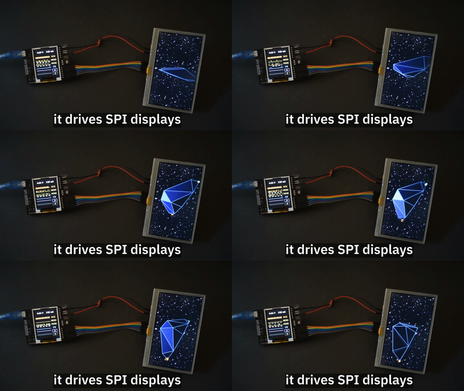
This SPIDriver It uses a standard FTDI USB serial chip to talk to the PC, so no special drivers need to be installed. The board includes 3.3 and 5 V supplies with voltage and current monitoring.
SPI flash is very common, and by using a test clip, SPIDriver makes it convenient to read and write SPI flash in-circuit. A short script is all it takes to read or write an Atmel’s flash and SPI LED strips are also easy to hook up to the SPI Driver, You can also be able to control them directly which makes them much more fun!
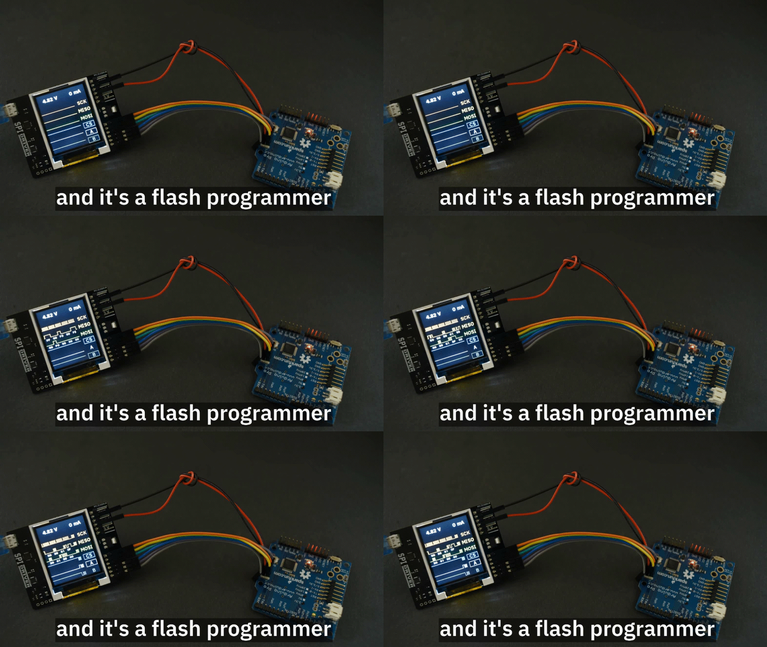
It’s fast enough to smoothly animate long strips and achieve POV effects. Short strips can be powered directly by the SPIDriver’s beefy 470 mA built-in supply.
All these features will help you will be able to transmit data with SPI with ease!
Examples of SPI in Microcontrollers
To end off, let us look at how SPI is being used in microcontrollers:
XIAO Series
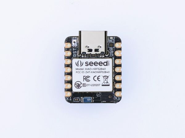
All the XIAO Series Microcontrollers that support I2C, UART, or SPI, and here’s the link for you to take a look at it Seeed Studio XIAO Series. And now for most of the XIAO Series is Free Shipping!
- Thumb-sized form factor, only 20×17.5mm. Made for space-constrained scenarios.
- Up to 11 available IOs support multiple interfaces, including analog, digital, IIC, UART, SPI, and more.
- Powerful core with a strong performance for diverse and complex applications.
- Single-sided components, surface mounting design. Easily integrate XIAO into other boards for mass production.
MCP 3008 / Grove I2C ADC
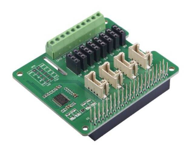
- Seeed does offer a similar product which has the same functions: Grove I2C ADC but its communication peripheral is I2C.
- It is 10 bit 8-channel analog-to-digital converter (ADC).
- For the MCP 3008, it connects to the Raspberry Pi using an SPI serial connection. Done by using the hardware SPI bus or any four GPIO pins and software SPI to connect to the MCP 3008.
Serial CAN-BUS Module based on MCP2551 and MCP2515

- The Serial CAN Bus module provides your Arduino with CAN bus capabilities and allows you to hack your vehicle. It lets you to read and write messages to the CAN bus.
- CAN bus is a messaging protocol system that lets various microcontrollers and sensors within a vehicle to talk to each other. CAN provides long-distance, medium communication speed, and high reliability.
- This Serial CAN Bus module can also be connected to your Arduino through the on-board Grove connector.
Interfaces with microcontrollers via SPI.
ENC28J60 OVERLAYS HAT for Raspberry pi

- This product by Seeed, The Pi zero ENC28J60 is a simple Network Adapter module for Pi zero and its very easy to assemble and configure.
- It allows your Raspberry Pi zero to access the network smoothly, and it is easy to do system updates and software installation operations.
- Microchip’s ENC28J60 is a 28-pin, 10BASE-T stand-alone Ethernet controller with an SPI interface.
- The SPI interface serves as a communication channel between the host controller and the ENC28J60.
Summary
That’s is all about SPI – Introduction to Serial Peripheral Interface! If you have any questions regarding SPI, you can comment down in the comments section down below!
Interested in other communication peripherals like I2C? Check out our other guide on I2C Communication – All about I²C with Diagrams.
Do not know what are the differences between the different communication peripherals UART, I2C and SPI? Check out our guide on UART VS I2C VS SPI – Communication Protocols and Uses


