L298, a Dual H-Bridge Motor Driver module
Ever wondered how do DC motors, relays and stepper motors operate? It’s all the works of L298! Learning how to control your DC motors would be so easier after you learn how to use L298.

Through this article, you will learn all about L298 Dual H-Bridge Driver. In this blog, we will be covering:
- What is DC Motor?
- What is L298 Dual H-Bridge Driver?
- Characteristics of L298
- L298 Pin-out
- L298n Motor Driver
- How does L298n motor driver work?
- Application of L298n Motor Driver
- Control DC motor with L298n motor driver and Arduino
- Comparison with other Motor Drivers
What is DC Motor?
DC motors are motors that operate on Direct Current(DC). DC motors are available in several different configurations from tiny little motors to absolute huge ones. DC motors can be used in robot basics, quadcopters, model planes and boats.
How does a DC motor work?
(Source: Renesas)
- DC motors consist of coils of wire
- Coils connected to the commutator
- Coils are surrounded by a pair of magnets or a stator
- DC current applied to the Commutator
- The magnetic field is formed in coils
- Coil magnetic interact with magnets(“stator”)
- The direction of rotation can be reversed by reversing the polarity on the motor’s contacts
For more information, please refer to Helen’s blog, Choosing the Right Motor for Your Project – DC vs Stepper vs Servo Motors.
What is L298 Dual H-Bridge Driver?

- L298 is a high voltage and high current motor drive chip which receives TTL logic signals.
- They are mostly used when
- It is needed to operate different loads like motors and solenoid etc where an H-Bridge is required.
- High power motor driver is required.
- Control unit can only provide TTL outputs.
- Current control and PWM operable single-chip device are needed.
- It has two enable inputs to enable or disable the particular device attached at its output independently.
Thus, H-Bridge is basically used to control the rotating direction in DC motors.
Characteristics of L298
The main features of the L298n Module are:
- High working voltage – can reach up to 46v
- Large output current
- Instantaneous peak current can reach 3A
- Continuous working current can reach 2A
- 25W Rated Power
- High-Voltage and Current full-bridge driver with 2 H-bridges used to drive inductive loads like DC and Stepper Motors.
- Controlled with standard logic level signals
- 2 enable control terminals to enable or device without inputting signals.
- Able to drive a two-phase stepper motor, four-phase stepper motor or two DC motors
- Has a high-capacity filter capacitor and freewheeling diode to protect devices from the reverse current of an inductive load.
- Built-in stabilivolt tube 78M05 can be used to obtain 5v from the power supply. (Must be used with an external 5v logic supply when the drive voltage is greater than 12v to protect the chip)
L298 Pin-out
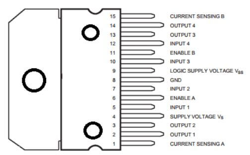
The pin functions are:
| Pin-Number | Name of Pin | Description |
| 1 15 | Sense A Sense B | Used to connect the sense resistor through this pin to the ground to control the current of the load. |
| 2 3 | Out 1 Out 2 | Output of bridge A, which is the current that flows through between these two pins which is monitored at pin 1 |
| 4 | Vs | Supply voltage during power output stages (non-inductive 100nF capacitor must be connected between pin and ground) |
| 5 7 | Input 1 Input 2 | TTL compatible inputs of Bridge A |
| 6 11 | Enable A Enable B | TTL Compatible Enable Input |
| 8 | GND | GND (Point where all voltages can be measured from) |
| 9 | Vss | Supply Voltage for Logic Blocks (non-inductive 100nF capacitor must be connected between pin and ground) |
| 10 12 | Input 3 Input 4 | TTL Compatible Inputs of Bridge B |
| 13 14 | Out 3 Out 4 | Outputs of the Bridge B. Current that flows through here are monitored at pin 15 |
L298n Motor Driver
The L298 module is mostly used to design motor drivers. Here at Seeed, we do offer various L298n Motor Drivers.
L298 Dual H-Bridge Motor Driver
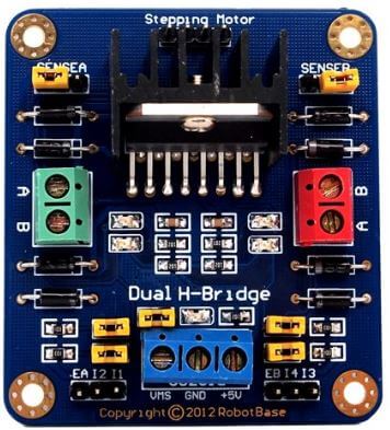
- Double H driver module uses ST L298N dual full-bridge driver, an integrated monolithic circuit in a 15- lead Multiwatt and PowerSO20 packages.
- It is a high voltage, high current dual full-bridge driver designed to accept standard TTL logic levels and drive inductive loads such as relays, solenoids, DC and stepping motors.
Motor Driver L298 Module – .NET Gadgeteer Compatible

- This motor driver module controls the speed and direction on 2 DC motors, up to 40V 3A.
- The module itself is powered and controlled from a gadgeteer mainboard but the motors are powered from a separate power source.
Grove – I2C Motor Driver

- It directly controls Stepper Motor or DC Motor. Its heart is a dual channel H-bridge driver chip(L298N)that can handle current up to 2A per channel, controlled by an Atmel ATmega8L which handles the I2C communication with platforms such as Arduino.
- Both motors can be driven simultaneously while set to a different speed and direction. It can power two brushed DC motors or one 4-wire two-phase stepper motor.
How does l298n motor driver work?
The schematic diagram below shows L298n Motor Driver internal structure and working flow:
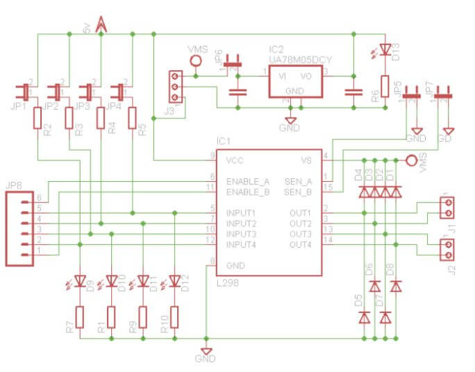
- The control mode and state of motor A is shown in the table below:
| Motor 1 (IN1), Motor 2 (IN3) | Motor 1(IN2), Motor 2 (IN4) | Motor Rotation |
| 0 | 0 | Stop Rotation |
| 0 | 1 | Clockwise |
| 1 | 0 | Anticlockwise |
| 1 | 1 | Stop Rotation |
- As seen from the table, the rotation direction is controlled by the control pin IN1 and IN2 for motor 1 while control pin IN3 and IN4 for motor 2.
- When enabled signal = 1
- IN1 and IN2 are 00 or 11 it means the motor is in brake state
- IN1 is 0 and IN2 is 1 it means motor A will rotate clockwise
- IN1 is 1 and IN2 is 0 it means motor A will rotate anticlockwise
- Motor B control method is the same as motor A
- Motor speed can also be controlled by the module PWM control pin (ENA for Motor 1, ENB for motor 2)
- When regulating speed, IN1 and IN2 rotational direction must be first confirmed and output PWM pulses for enabled terminals.
How does l298n motor driver work with DC motor?
Let’s take a look at how the l298n H-bridge motor driver works with DC motor.
In order to simplify things, I have drawn one set of the H-bridge driver with 4 switches. Why is it called H-bridge? As you can see there is a letter H in the configuration with the motor sitting in the bridge part of the letter H. How does it work?
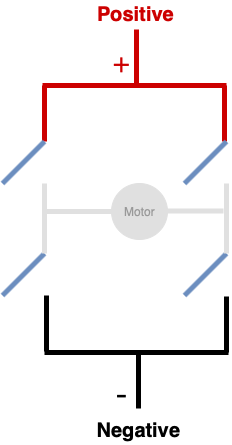
Let’s apply a positive voltage to the top of the H-bridge and apply a negative voltage to the bottom.
Now, what happens when we close these two switches?

The positive is applied to the left side of the motor and the negative is applied to the right side. In this case, the motor will rotate clockwise.
Vice versa, if you close the other two switches and leave these two open.
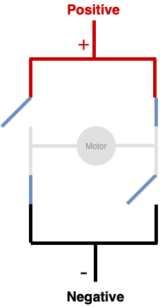
Now, the positive is applied to the right side of the motor and the negative is applied to the other side. In this case, the motor will rotate anti-clockwise.
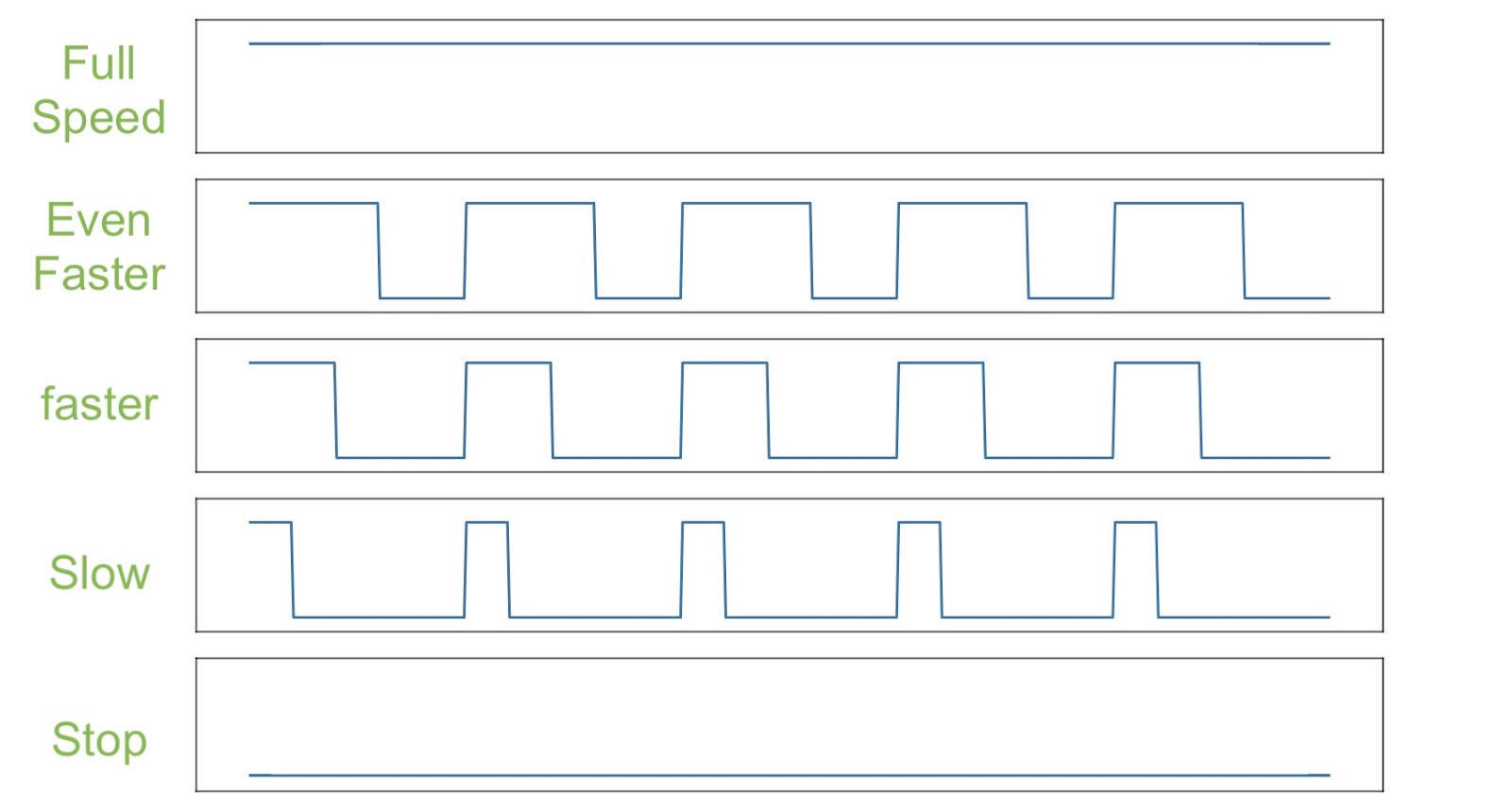
Pulse Width Modulation(PWM)
The speed of the motor is determined by the width of the PWM pulse sent to the “Enable” input of the L298N motor driver. The wider the pulses, the faster the motor will spin. Thus, PWM allows you to control the speed.
Application of L298n
L298n Motor Drivers are used everywhere in our everyday life ranging from vending machines to robots. You can also play around with the L298n to control DC motors right at home with the tutorial below
Controlling DC Motors with Arduino
With the L298n dual H-bridge, it allows you to switch the direction of the current which means with a motor, you can make it spin in both directions. In addition, with PWM input, you can use an Arduino to make it spin at any speed.
- What will you need?
- Step 1- Set the address by dial switch which is a new function added to our new I2C motor driver

- Step 2 – Connect Grove – I2C Motor Driver V1.3 to port I2C of Grove-Base Shield.
- Step 3 – Plug Grove – Base Shield into Seeeduino.
- Step 4 – Connect Seeeduino to PC via a USB cable
- Step 5 – Download Grove_I2C_Motor_Driver_v1_3 Library from Github.
- Step 6 – Refer How to install library to install library for Arduino
- Step 7 – Copy the code into Arduino IDE and upload. If you are unsure how to upload the code, please check how to upload code.
Code

Functions to control DC motors

- With the speed function – you can drive one motor at the speed you want
- motor_id represents which motor to use (MOTOR1/2)
- _speed represents the speed you can set. It can be -100 to 100, when speed is >0 DC motor will run clockwise while if speed <0, DC motor will run anticlockwise. The bigger the value, the faster it is.
- With stop function – you can choose to stop running a DC motor
- motor_id represents which motor to use (MOTOR1/2)
There you go! You now have your very own DC motor controlled using the Seeeduino with an I2C motor driver!

Interested in doing more with your L298 motor driver? You can click here to learn how to drive a stepper motor and play with Codecraft using the L298n Motor Driver: Seeedstudio Wiki – Grove – I2C Motor Driver V1.3
Comparison with other Motor Drivers
With so many motor drivers currently such as Servo Motors and stepper motors, what really are the differences between the motor drivers and which one to choose? No worries, as we have crafted a table just for you to compare the various motor drivers so you know which motor driver fits the best for your project.
| Type | Motor Drivers | Chip | Actuator | Working Voltage | Working Current |
|---|---|---|---|---|---|
| Grove | Grove – I2C Motor Driver | L298n | 2 DC motor or 1 Stepper | 6v to 15v | 2.0A each (Max) |
| Grove – I2C Motor Driver (TB6612FNG) | TB6612FNG | 2 DC Motor or 1 Stepper | 2.5v to 13.5v (5 Avg, 15v Max) | 1.2A (Avg) to 3.2A (Max) | |
| Grove – I2C Mini Motor Driver | DRV8830 | 2 DC Motor | 2.75v to 6.8v | 0.2A to 1A each | |
| Shield | Motor Shield V2.0 | L298n | 2 DC motor or 1 Stepper | 6v to 15v | 2.0A each (Max) |
| 4A Motor Shield | MC33932 | 2 DC Motor | 6v to 28v | 5.0A each (Max) | |
| Brushless Motor Shield (TB6605FTG) | TB6605FTG | 1 DC Brushless Motor | 9v to 24v | – |
Summary
With all the knowledge of L298n motor driver in your hands, you can now start building your very own robotic projects! You can check out the L298n data sheet for more detailed information on the L298 over here: L298 Datasheet