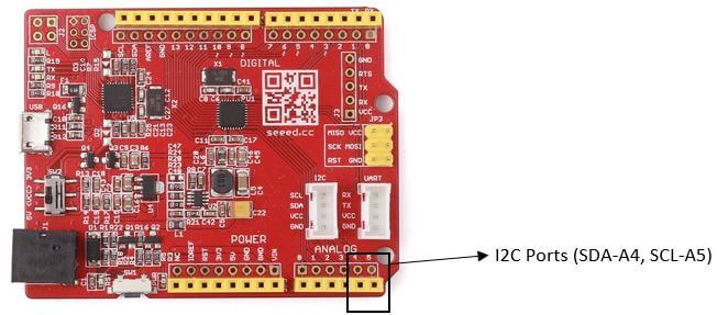
I2C Communication – All about I²C with Diagrams
As an engineer, you will have to use I2C communication one day. I2C is
As an engineer, you will have to use I2C communication one day. I2C is one of the most popular communication peripherals due to its fast speed and flexibility.
Today, through this blog, you will learn all about I2C, its basics and how it works.
What will be covered:
- Interface
- Characteristics
- Communication protocol
- Advantages and disadvantages
- I2C examples and implementation
Without further ado, let us jump right into what is an I²C?
What is an I²C? (Signals)
- I²C stands for Inter-integrated-circuit
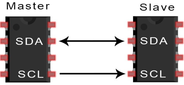
- It is a serial communication interface with a bidirectional two-wire synchronous serial bus normally consists of two wires – SDA (Serial data line) and SCL (Serial clock line) and pull-up resistors.
- They are used for projects that require many different parts (eg. sensors, pin, expansions, and drivers) working together as they can connect up to 128 devices to the mainboard while maintaining a clear communication pathway!
- It is used to connect various low-speed devices together like microcontrollers, EEPROMs, A/D and D/A converters, etc.
- Unlike UART or SPI, I2C bus drivers are open-drain which prevents bus contention and eliminates the chances for damage to the drivers.
- Each signal line in I2C contains pull-up resistors to restore the signal to a high of the wire when no device is pulling it low.
- All transfers are initiated and terminated by the “master device”; the “master device” can write data to one or more “slave devices” or request data from the “slave devices”. “Master” and “Slave” are not fixed in the system. In fact, any device can be used as “Master” or “Slave” as long as it is configured with appropriate hardware or firmware.
- The data is transmitted in one byte, and each byte is followed by a 1-bit handshake signal as the ACK/NACK bit (acknowledgement/no response).
Why use I2C?
- The I2C bus is currently still a common communication peripheral used by various circuits and is simple to implement. No matter how many devices are connected to the bus, only two signal lines (clock SCL and data SDA) are needed.
- It is a true multi-master bus, which is superior to SPI.
- In addition, the I2C interface is also flexible which allows it to communicate with slow devices while also having high-speed modes to transmit large data. The transmission rate can reach 100kbit/s in standard mode, 400kbit/s in fast mode, and 3.4Mbit/s in high-speed mode;
- Because of how flexible it is, I2C will always remain as one of the best communication peripheral to connect devices.
Characteristics
| Wires | 2 (SCL and SDA) |
| Data Frame Size | 8 Bits packets |
| Maximum speed | Standard mode = 100 Kbps |
| Fast Mode = 400 Kbps | |
| High-Speed mode = 3.4 Mbps | |
| Ultra-Fast Mode = 5 Mbps | |
| Strict Baud Rate? | No (Compared to UART) |
| Number of Masters | Unlimited |
| Number of Slaves | Depends (Up to 127 but can be more up to the capacitance of 400 pf) |
I²C communication protocol
How does I²C work?
- I2C data is transferred in messages which are broken up into data frames.
- Each message contains:
- Start condition
- Stop condition
- Read and write bits
- ACK/NACK bits
- Address of the Slave
- Data frame
Start and Stop Condition
- Start Condition:
- The transmission will start when the master device switches the SDA line from high voltage level to low voltage level then switches the SCL line from high to low.
- Signals to other slave devices that a transmission is going to happen.
- If two masters send a start condition at one time wants to take ownership of the bus, whoever pulls the SDA low first “wins”
- Stop Condition:
- A stop condition will be transmitted after all the data frames have been sent.
- The SCL line will switch from a low voltage level to high first before the SDA line switches from a low voltage to high
- Value on SDA should not change when SCL is high during normal data writing operation as it can cause false stop conditions.
Read/Write Bit
- Single bit specifying whether the master is transmitting (write) data to the slave (low voltage level) or requesting (read) data from it (high voltage level).
ACK/NACK Bit
- Sent by the receiving device after each frame to signal to the sender whether the data frame was successfully received (ACK) or not (NACK)
Addressing
- Compared to SPI, I2C do not have slave select lines which cause the slave devices not being able to know when data is being sent to him instead of other slaves.
- To solve this problem, I2C uses an address frame which is the first frame after the start bit in a new message.
- Master devices will first send the unique address of the slave it wants to communicate with. I
- If the address does matches with the slave own address, it will send an ACK bit back to the master device.
- If it does not match, the slave will do nothing which leaves the SDA line high.
Addressing:
The master device sends the address of the slave device with which it wants to communicate to each slave device connected to it. The slave device compares the received address with its own address.
- If the match is successful, the slave device knows that it will establish communication with the master device. It will send an ACK bit back to the master device.
- Compared to SPI, I2C do not have slave select lines which cause the slave devices not being able to know when data is being sent to him instead of other slaves.
- To solve this problem, I2C uses an address frame which is the first frame after the start bit in a new message.
- Master devices will first send the unique address of the slave it wants to communicate with. I
- If the address does match with the slave own address, it will send an ACK bit back to the master device.
- If it does not match, the slave will do nothing which leaves the SDA line high.
10-bit device address
- I2C normally has a 7-bit address and there are only 127 different I2C devices. However, in reality, there are way more types of I2C devices and an I2C device has a high chance of having the same address on a bus.
- In order to overcome this limitation, many of the devices use dual address through external configuration pins and also a 10-bit address scheme.
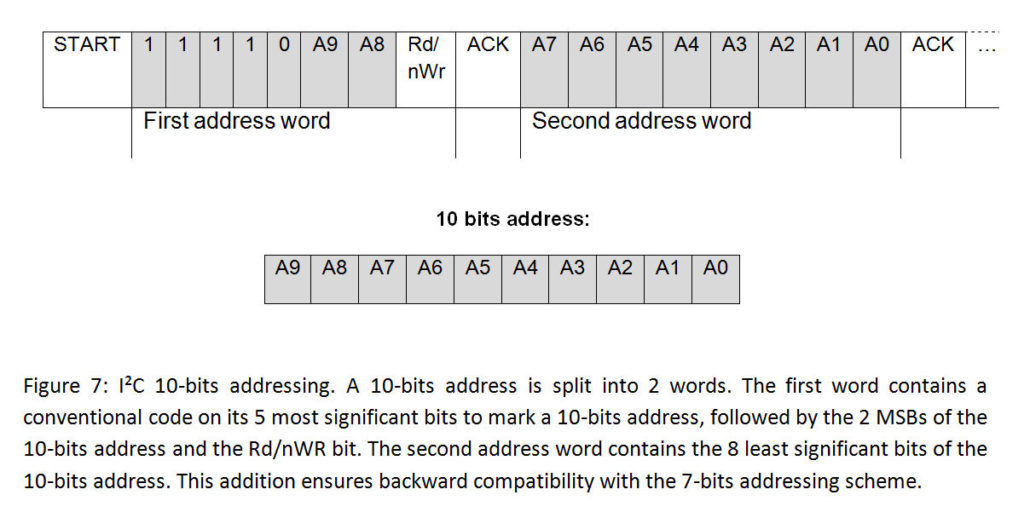
- The 10-bit address scheme has two effects on the normal I2C protocol:
- The address frame now has two bytes instead of 1 byte.
- The first five most significant bits of the first byte is used to identify the 10-bit address with the convention being “11110”.
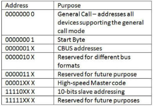
- I2C also have addresses that are reserved for special purposes
Data Frame (data to be transmitted)
- After the address frame has been sent and the master device receives an ACK bit from the slave, data will begin being transmitted which are 8 bits long with the most significant bits (MSB) being sent first.
- While the master device will be generating clock pulses at regular intervals, data are sent on the SDA by the master or the slave depending on the Read/write bit.
- Each data frame is followed by an ACK/NACK bit to signal whether the data has been received successfully. The ACK bit must be received by either the master or the slave before the next data frame can be sent
- After this process has been completed, the master will send a stop condition to the slave which will end the transmission.
Step by step of I2C communication
- Step 1: A start signal will be generated by the master device which signals to the other devices to start listening to the bus and prepare to receive data. (SCL high, SDA switch from high to low)
- When a start signal condition is transmitted, the bus will enter a busy state where the current data transfer is limited to only the selected master and slave. It is only after a stop condition is generated where the bus will be released and be in an idle mode again.
- Step 2: The master device will send a 7-bit device address plus one bit of reading and write the data frame to every device. The bit will also indicate the direction of the next data transmission. 0 = Master device writes data to the slave devices. 1 = Master device reads data to the slave devices.
- Step 3: Each slave compares the address sent by the master with its own address. The slave device that successfully matches the address returns the ACK bit by pulling the SDA line low.
- Step 4: When the master device receives an acknowledgement signal from the slave device, it will start transmitting or receiving data. Below is a diagram of the process of transmitting data to the specified device.
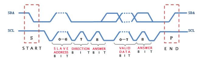
- Step 5: After transmitting each data frame, the receiving device returns another ACK bit to the sender to confirm that the frame is successfully received, and then the sender continues to transmit the data frame, and so on.
- Step 6: When the data transfer is completed, the master device will send a stop signal which signals the release of the bus to other devices and the bus will enter an idle state.
I²C bus operation
The operation of the I2C bus is a read and write process between master and slave devices. There are mainly divided into 3 processes:
- Master device writes data to the slave device:

- The master device reads data from the slave device:

- Repeated start conditions:
- Used during the idle state of the bus where no other master can assert control of the bus and no stop condition is present
- This is a single master system. Repeating/restarting conditional mechanisms are more efficient than using a stop signal to end the transfer and starting the bus again
- For example,
- Master device writes data to the slave device then restarts the start condition, and then reads data from the slave device OR
- The master device reads data from the slave device then restarts the start condition, and then the master device writes data to the slave device:

Clock Stretching
- In I2C, the master device controls the clock speed and the signal can only be transmitted by the master device.
- Clock stretching is used to allow the slave device to control the clock line by pressing on the clock line to force the master device to enter wait until it releases the clock line where communication can then continue.
- This is used when a slave device is unable to keep up with the speed of the master device in the I2C structure.
Fast Mode (=400 Kbps)
- Fast mode devices can be synchronized with 400kbit/s transmission.
- Devices with fast mode are backwards compatible and can communicate with standard mode devices in the I²C bus system at 0~100kbit/s.
- However, standard mode devices are not upward compatible, so they cannot work in a fast mode I²C bus system.
High-speed mode
- Speed is one of the factors that limit the I2C bus application. Using a pull-up resistor which sets a logic 1 limits the maximum transfer speed of the bus which is why the high-speed mode at a speed of 3.4 Mbit/s is introduced.
- It can be switched by the master which will first transmit a high-speed signal while in low-speed mode (eg. fast mode)
- In order to shorten the signal period and increase the bus speed, this mode must be used with an additional I/O buffer.
- During this mode, bus arbitration can be masked out. (Refer to the bus standard documentation for more information.
Advantages and Disadvantages of I2C
Advantages
- Low pin/signal count even with many devices on the bus
- Flexible = supports multi-master and multi slave communication
- Simple = uses only 2 wires
- Adaptable = Adapt to the needs of various slave devices.
- Reliable = ACK/NACK confirms that every frame has been successfully transmitted.
- Devices can be installed or removed on the bus at any time.
Disadvantages
- Slower speed compared to SPI as it uses pull-up resistors.
- Open-drain design = limited speed.
- Requires more space due to the use of resistors
- Complex as the number of devices increase.
Examples of I2C in microcontrollers
Because of how flexible it is, I²C will always remain as one of the best communication peripheral to connect devices. Below are 3 examples of how I²C is used in microcontrollers:
Grove – I2C Hub (6 Port)
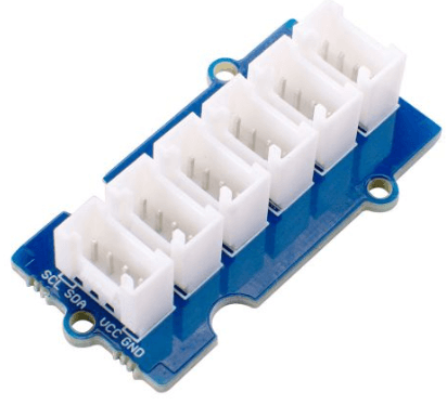
- I2C is a very popular communication protocol. In the Grove system, I2C is used by 80+ sensors for communication, 19 of which are related to environmental monitoring.
- Today more and more MCUs uses 3.3V communication levels, but the traditional Arduino Uno still uses 5V, which leads to many modules, especially sensor modules, need to be levelled when using them.
- We actually worked on this area, and now most of the Grove sensor modules have a level shifting function, and users do not need to consider the use of 3.3V or 5V MCU when using it. This is in line with Grove’s motto; plugin, and use it, it’s that simple. For a more detailed sensor review compatibility, you can view our Grove Selection Guide.
MCP 4725
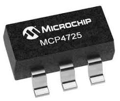
- Low power, high accuracy, single channel with a 12-bit buffered voltage output digital to analog converter (DAC) with non-volatile memory.
- Allows us to read signals from analog sensors and convert into digital language.
- Uses a standard I2C pinout
Raspberry Pi I2C and Arduino I2C
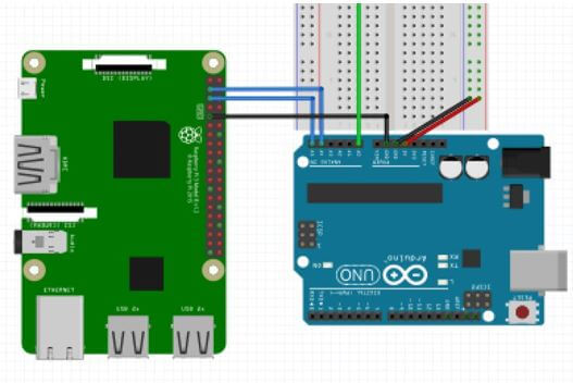
- I2C is also used and compatible with the Raspberry Pi and Arduino to allow data exchange between microcontrollers and peripherals with a little wiring.
- Raspberry Pi = It’s a low-cost, credit-card sized computer that can be plugged into a computer monitor or TV.
- Arduino = Open-source electronics platform that is able to read inputs like light on a sensor, finger on a button and turn it into an output. (activate a motor – turning on a LED)
- With I2C you can connect both devices together!
I2C Arduino
- I2C communication can also be used between two Arduino boards or other devices.
- I2C makes connecting sensors and displays together with the Arduino simple as it only involves two wires and it can reduce pin counts too even with numerous devices on the bus
- They are used only for short-distance communication with a synchronized clock pulse and mainly used to communicate with sensors or other devices which have to send information to a master.
- There is also a standard I2C library for the Arduino which is called the wire library which allows you to communicate with I2C devices with your Arduino easily.
Seeed I2C Products
- Over here at Seeed, we do offer various I²C products! For example, we have two of our amazing I²C products as shown below:
I2C LCD (With universal Grove cable)
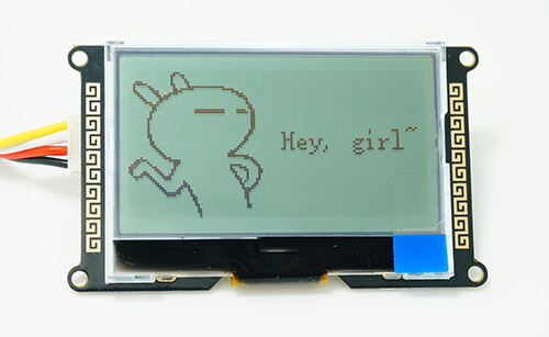
- With this I2C LCD which is an easy-to-use display module, It can make creating display much more easy.
- We developed the Arduino library for I2C LCD where users just need a few lines of the code to achieve complex graphics and text display features.
- In addition, we also develop the data converting software (bitmap converter) which supports PC Windows, Linux, Mac OS. Through this software, you can put your favourite picture on I2C LCD, without the need for complex programming.
- It is also supported by Grove which is our very own modular, standardized connector prototyping system.
I2C Driver/Adapter-Easily Driver I2C Devices
- We have our very own I²C Driver which is an easy-to-use, open-source tool for controlling I²C devices.
- It works with Windows, Mac, and Linux, and has a built-in colour screen that shows a live “dashboard” of all the I²C activity.
- It uses a standard FTDI USB serial chip to talk to the PC, so no special drivers need to be installed. The board includes a separate 3.3 V supply with voltage and current monitoring.
- Afraid that your I²C connection may go wrong? Do you want to avoid the painful debugging? Well, this I²CDriver right here makes I²C much more user-friendly and it can prevent just that.
If you are interested to find out more about our I²C products and what we offer, you can check out our Bazaar website over here:
Seeed Studio I2C products
Related Products (Not I2C)
SPI Driver/Adapter-Easily Driver SPI Devices
- We also offer a driver an SPI Driver open-source tool for controlling SPI devices
- It has the same built-in colour screen that shows a live logic-analyzer display of all SPI traffic. It also uses a standard FTDI USB serial chip to talk to the PC, so no special drivers need to be installed.
- You can directly control LEDs and LCD displays without having to go near a microcontroller. If you need to examine, backup, or clone an SPI flash, SPIDriver is the ideal tool
Summary
And that’s all on I2C! We’ve covered everything you need to know about I2C, from its interface to its implementation and examples. Hope that you’re able to understand I2C better now. Should you be interested in blogs as such, do check out the link below!
Resources
If you wish to find out more about other communication peripherals like SPI and UART and its comparison against I2C, you can check out my other article which we also have more examples of I2C like ADS1115, MCP23017 and PCF 8574 here:
UART vs I2C VS SPI – Communication Protocols and Uses