Resistor Color Codes and Chart for 3, 4, 5, and 6 Band Resistors
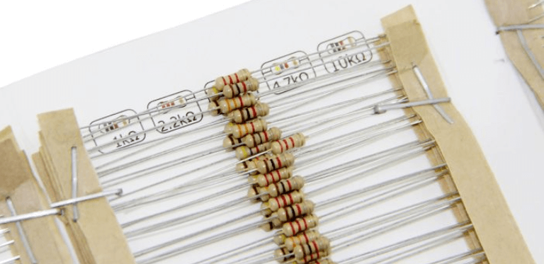
Did you buy a pack of 500 resistors, only to be mortified to discover how clueless you are about those colorful rings on your new resistors? You wonder, why couldn’t they just print the resistance value on the resistor and make life easier for everyone? If reading resistor color codes sounds foreign to you, then read on!

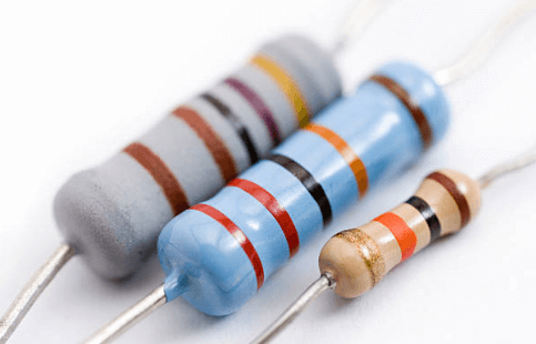
As resistors are small, it is pretty difficult to print numbers or the resistance value onto the small surface area of the resistor. Thus, instead of directly printing numbers onto the resistor, resistor color codes are used. Resistors can have 3 bands, 4 bands, 5 bands or 6 bands. The colored bands are used to denote the resistance, tolerance and the temperature coefficient.
We have put together a simple guide to explain the calculation behind resistor color codes. Reading resistor color codes can become easy once you understand the math behind each colored band.
Getting Started: Resistor Color Code Chart
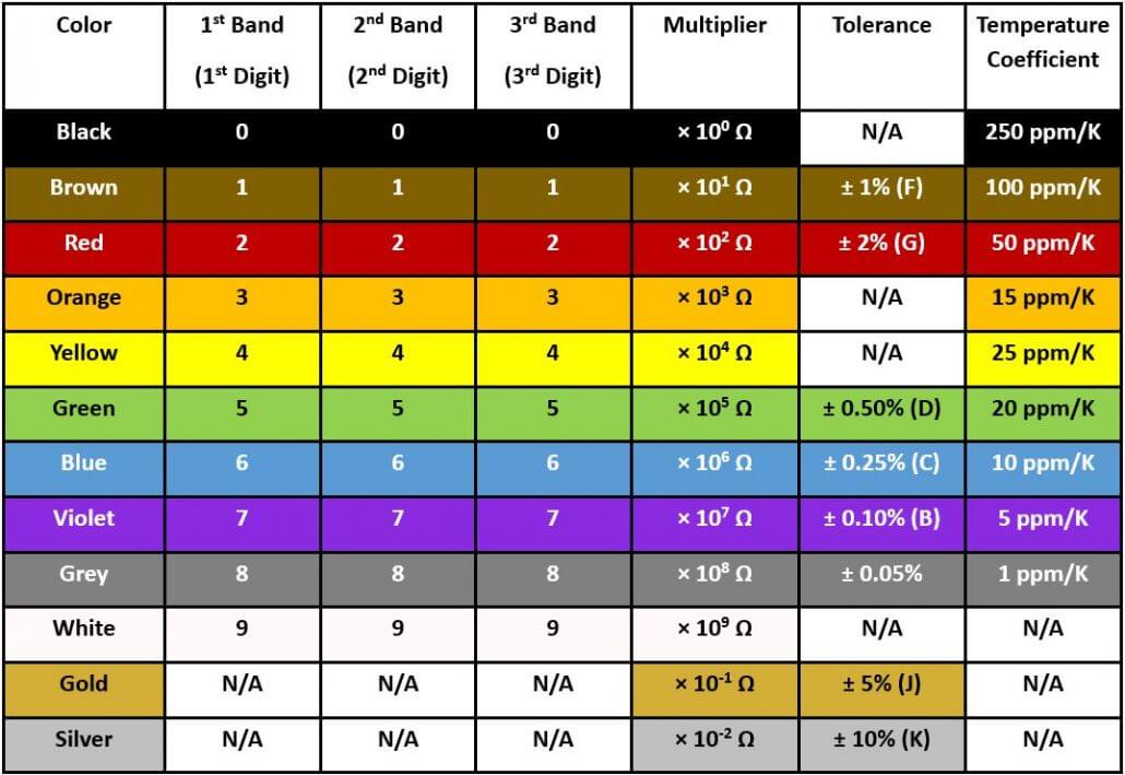
Before getting to the math bit, you have to know about an important tool known as the Resistor Color Code Chart. Similar to how the periodic table is indispensable to a chemist, the Resistor Color Code Chart is your best friend when it comes to decoding a resistor’s code. You will find yourself referring to this chart frequently, as values needed to calculate the resistance value are compiled on this chart. More details on how to use it when we explore examples in the later section!

Is there an easy way to remember these colors?
Absolutely. If you find it difficult to remember what colors there are in resistor color codes, try these mnemonics.
Acronym: BBROYGBVGW
Phrase: Bad Beer Rots Our Young Guts But Vodka Goes Well
B.B. Roy of Great Britain has a Very Good Wife
Bad Boys Race Our Young Girls But Violet Generally Wins
Getting Started: Identifying the first colored band
This is the question that usually arises first because we can’t start calculating the resistance from the resistor color code if we can’t get their reading direction right in the first place. Fortunately, the resistor color code has some visual clues that give the answer away!

- The most obvious trick to this is that there is an increased space that occurs before the tolerance band. The bands are not regularly spaced apart and can be seen as being grouped into two. Put the larger group on the left and read the resistor from left to right.
- The first band is usually always closest to the end. But this may not be the case all the time.
- If you find a gold or silver color band on your resistor, it is definitely the tolerance band and the last band on the resistor. So, they belong to the right side of the resistor and again, read the resistor from left to right.
Also, be sure to check your manufacturer’s documentation to be sure about the resistor color codes used. If none of the ways above are helpful, you can always rely on a multimeter to measure the resistance. Sometimes this might be the only way to figure out the resistance, especially when the color bands are scratched or burnt off.
Calculating Resistor Color Codes
3 Band Resistor Color Code
For a 3-band resistor color codes, the first two bands always denote the first two digits of the resistance value while the third band represents the multiplier.

AB × C ± 20%
10 × 101 ± 20% = 100 Ω ± 20%
Bands:
A: 1st band – 1st significant digit
B: 2nd band – 2nd significant digit
C: 3rd band – multiplier
In the example we have, the bands are brown, black and brown. The first band is the brown band closest to the edge. We look up our resistor color code chart, and find that brown has the 1st significant value of 1 and black has the second significant value of 0. The third band is brown, which means that the multiplier is 1. Using the formula, the resistance is thus calculated to be:
As the 3-band resistor has no fourth tolerance band, the default tolerance is taken to be at 20%.
4 Band Resistor Color Code
The 4-band resistor color code is the most commonly used resistor. Similar to the 3 band resistor, the first two bands always give the first 2 digits of the resistance value. The third band represents the multiplier while the fourth band represents tolerance.

AB × C ± D%
12 × 105 ±5% = 1,200 kΩ ± 5%
Bands:
A: 1st band – 1st significant digit
B: 2nd band – 2nd significant digit
C: 3rd band – multiplier
D: 4th band – tolerance
For a 4 band resistor color code, we can begin by first finding the tolerance band as it is usually gold or silver. The tolerance band is also easily identified due to the increased gap between the tolerance band and the multiplier band. In this example, it is gold and thus gives a tolerance of ±5% when we look up the resistor color code chart. Starting from the other end, the first band is thus identified to be brown which has a 1st significant digit of 1. The second band is red and has a second significant digit of 2. The 3rd band is green which means that the multiplier is 105. Using the formula. The resistance obtained is 12 × 105 = 1,200 kΩ. Lastly, the tolerance band which we identified to be gold gives a tolerance value of ±5%.
Sometimes for a 4 band resistor color code, the tolerance band can be left blank, resulting in a 3-band resistor. In this case, the resistance value would remain the same, except that the tolerance would be ±20% as if it were a 3-band resistor.
5 Band Resistor Color Code
5 band resistors are resistors with higher precision, and they have an extra band for a 3rd significant digit. As such, the first three bands denote the significant digits of the resistance and everything else shifts to the right, making the fourth band the multiplier and the fifth band the tolerance.

ABC × D ± E%
475 × 100 ± 1% = 475 Ω ± 1%
Bands:
A: 1st band – 1st significant digit
B: 2nd band – 2nd significant digit
C: 3rd band – 3rd significant digit
D: 4th band – multiplier
E: 5th band – tolerance
In this example, the tolerance band is brown and is identified by the increased space between itself and the multiplier band. From the resistance color code chart, we obtain a tolerance value of ±1% for brown. Beginning from the other end, the first band and second band is yellow and violet, which gives the 1st and 2nd significant digit of 4 and 7 respectively. The extra third band is blue and so the 3rd significant digit is 5. The fourth band is black and gives the multiplier value of 100. Using the formula, we get the resistance value of 475 × 100 = 475 Ω.
6 Band Resistor Color Code
A 6 band resistor is essentially a 5 band resistor with an extra ring that denotes the temperature coefficient or sometimes, the failure rate. The most common color for the sixth band is brown (100 ppm/K), which means that for every 10℃ change in temperature, the resistance value changes by 0.1%.

ABC × D ± E%, F
274 × 100 ± 2%, 250 ppm/K = 274 Ω ± 2%, 250 ppm/K
Bands:
A: 1st band – 1st significant digit
B: 2nd band – 2nd significant digit
C: 3rd band – 3rd significant digit
D: 4th band – multiplier
E: 5th band – tolerance
F: 6th band – temperature coefficient
For this example, the resistor color code bands can be grouped into 2 groups according to the space between the multiplier band and the tolerance band. Place the larger group on the left and the smaller group on the right and read the resistor from left to right. Again, we check the resistor color code chart for red, violet and yellow, and the first, second and third bands give the significant digits of 2,7 and 4 respectively. The fourth band is black, giving a multiplier value of 100. Hence, we will get a resistance value of 274 × 100 = 274Ω. The fifth tolerance band gives a tolerance value of ±2%. The sixth band is black and gives a temperature coefficient value of 250 ppm/K.
Resistor Color Band Exceptions
Zero-Ohm Resistors
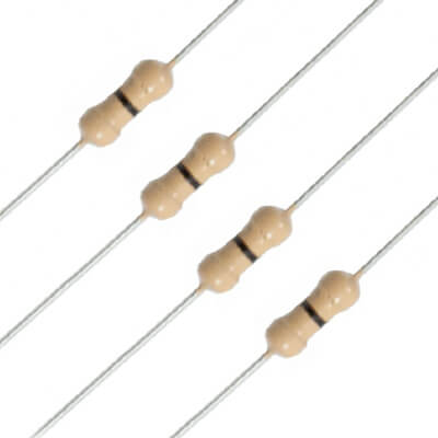
Zero-ohm resistors are resistors that can be easily recognized by their single black band. Basically, it is a wire link with the only function of connecting traces on a printed circuit board. But why not use a regular jumper wire for that purpose?

(Source: ES Mobile)
The reason behind why they are fashioned to look like resistors is because components in most printed circuit boards are placed using automatic insertion machines instead of being manually placed by hand. By looking like a resistor, manufacturers can make use of the same automated machine to place for placing components on a circuit board. This eliminates the need for a separate machine for installing jumper wires.
In addition, zero-ohm resistors can be more easily removed than jumper wires. This enables any design changes to be easily made if necessary. The zero-ohm resistor can be easily removed and replaced by new components.
Now that you are ready to decode any resistor color code that comes your way, you can take on that pack of 500 resistors from the Seeed Bazaar!
Is assembling these tiny resistors on your PCB board too troublesome? Have you ever wished that someone else could do it for you? If so, the Seeed Fusion PCB Assembly service might just be what you are looking for. Regardless of the complexity or quantity of your designs, your boards will be manufactured with the same care and quality control practices that Seeed uses for its own products. Simply upload your PCB design onto the Seeed Fusion online platform, and a competitive quote will be generated for you within a matter of seconds. Check it out here.
And now, try the service with absolutely no assembly costs for 5 boards, saving as much as 80% on the usual price. Take advantage of the offer today.
That’s all for our guide on resistor color codes! If you have any further questions or tips about how to use the resistor color codes to calculate resistance, feel free to drop us a message in the comments section below.

How if only have 2 colour only
If the body is a greyish color it could be a power resistor that’s burnt up the other color bands. It’s not really a two-band resistor.
I think the color code is wrong.
A resistor brow black brown is a 100 Ohms
You might want to review.
Yes, you are right since the multipler for brown is 10. Thank you for pointing it out!